What you need
-
-
-
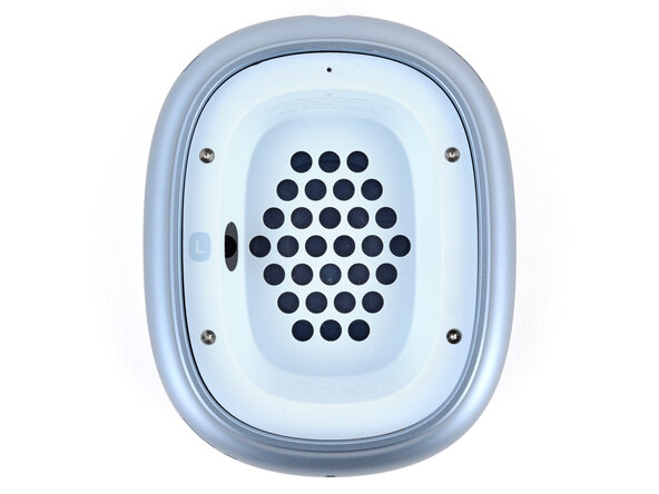
Lift the left earpad (labeled L) straight up and remove it.
 Ask FixBot
-
-
-
-
-
Insert a SIM eject tool, bit, or a small, straightened paperclip into the hole on the top edge of the right ear cup (labeled L).
-
Push down with your tool and pull the headband connector straight out of its socket.
-
-
-
-
-
Set the left ear cup down on a soft, clean cloth to prevent scratches and help stabilize the cup during your repair.
-
-
-
Use a P5 pentalobe screwdriver to turn (not remove) the four speaker housing screws to the unlocked position:
-
Turn the top left and bottom right screws counterclockwise.
-
Turn the top right and bottom left screws clockwise.
-
-
Tool used on this step:iOpener$14.95
-
Option 1: Apply a few drops of high-concentration isopropyl alcohol (>90%) in the gap around the perimeter of the speaker housing. Wait one minute to allow the alcohol to soften the adhesive.
-
Option 2: Heat the speaker housing with an iOpener or hair dryer. Focus the heat around the perimeter, applying small amounts for short periods of time.
-
-
Tool used on this step:iSesamo Opening Tool$10.99
-
Insert the flat side of your opening tool into the gap between the right side of the speaker housing and the lip of the ear cup (opposite the L marking).
-
Pry up the speaker housing until you can grip it with your fingers, applying constant pressure to allow the adhesive to separate.
-
-
-
Lift the speaker housing out of the ear cup to fully separate the remaining adhesive.
-
Flip the housing over the side of the cup and prop it up so you can access the cable.
-
-
Tool used on this step:FixMat$36.95
-
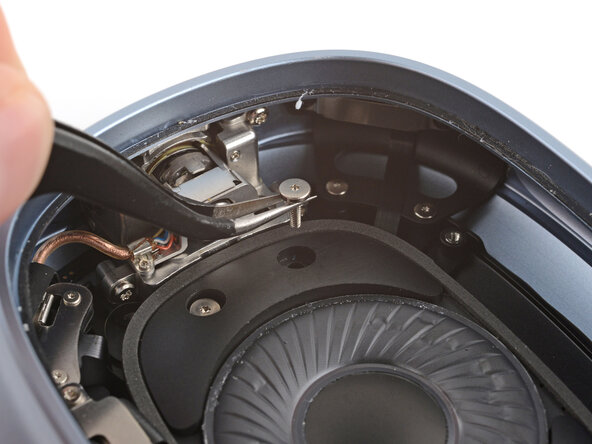
Remove the four screws securing the cable cover:
-
One 7.5 mm‑long Torx Plus 3IP screw
-
Three 1.7 mm‑long Torx Plus 1IP screws
-
-
-
Use tweezers to slightly lift the cover and slide it towards the center of the ear cup to remove it.
-
-
-
-
Use a spudger to pry up and disconnect the speaker housing press connector.
-
-
-
-
-
Use a Torx Plus 3IP screwdriver to remove three speaker driver screws:
-
Two 6.0 mm‑long screws
-
One 6.0 mm‑long screw that's slightly thicker than the other two
-
Remove the 5.1 mm‑long standoff screw using one of the two methods below:
-
Option 1: Stick a small flathead screwdriver into one of the four notches on top of the screw and use it to slowly turn the screw.
-
Option 2: Use a Torq-Set 6 screwdriver to remove the screw, applying constant downward force to avoid damaging the screw.
-
-
-
Lift the right edge of the speaker and remove it, being careful not to touch the diaphragm.
-
-
-
-
-
Remove the two Bluetooth board connector cover screws:
-
One 7.5 mm‑long Torx Plus 3IP screw
-
One 1.7 mm‑long Torx Plus 1IP screw
-
-
-
Use tweezers to slightly lift the cover and slide it towards the center of the ear cup to remove it.
-
-
-
Use a spudger to pry up and disconnect the press connector from under the cover you just removed.
-
-
-
Use a spudger to pry up and disconnect the press connector on the other end of the board.
-
-
-
Slide one arm of your angled tweezers under the metal neck of the coaxial connector (next to the one from the previous step) and lift straight up to disconnect it.
-
-
-
Use the point of a spudger to gently pull the copper hinge cable (in plastic tubing) out of its clip.
-
-
-
Use a Torx Plus 1IP screwdriver to remove the 3.0 mm‑long screw securing the Bluetooth board.
-
-
-
Stick the point of a spudger into the baord's screw hole near the hinge and pull the board towards the center of the ear cup.
-
Use your fingers to flip the board over the side so you can access the remaining connector.
-
-
-
Use the point of a spudger to press on alternating sides of the sliding connector tabs to "walk" it out of the socket.
-
-
-
-
-
Use a spudger and your fingers to lift all ends of the microphone cable until it fully separates from the ground wire shell.
-
-
-
Remove the five screws securing the ground wire shell:
-
One 11.8 mm‑long Torx Plus 2IP screw
-
Two 10.6 mm‑long Torx Plus 3IP screws
-
Two 9.5 mm‑long Torx Plus 3IP screws going into the side of the ear cup
-
-
-
Stick the point of a spudger into one of the ground wire clips screw holes and pull the board towards the center of the ear cup.
-
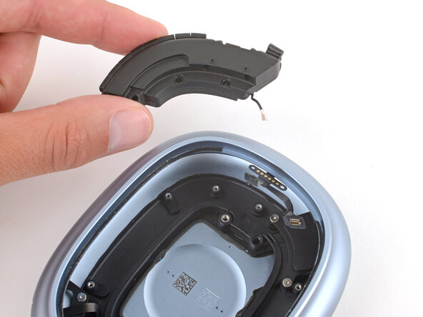
Use your fingers to remove the ground wire shell.
-
-