
Astro A40 TR Internal wiring components Replacement

What you need

  1. Astro A40 TR Internal wiring components Replacement, Speakers: step 1, image 1 of 2 Astro A40 TR Internal wiring components Replacement, Speakers: step 1, image 2 of 2
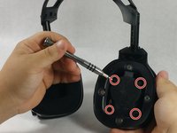
    • To access the speakers you need to disassemble the earpiece. First remove the foam ear piece by simply pinching the padding and pulling lightly until the magnets disengage.

  2. Astro A40 TR Internal wiring components Replacement: step 2, image 1 of 3 Astro A40 TR Internal wiring components Replacement: step 2, image 2 of 3 Astro A40 TR Internal wiring components Replacement: step 2, image 3 of 3
    • Remove the dust cover located on the speaker. Use the corner of the spudger to peel underneath the cover until you can lift it by hand. The cover is held onto the device with adhesive and should be removed slowly.

  3. Astro A40 TR Internal wiring components Replacement: step 3, image 1 of 2 Astro A40 TR Internal wiring components Replacement: step 3, image 2 of 2
    • Take off the front cover by removing the four screws located in a square formation on the surface of the device. Use the J00 Philips driver listed in the device page.

  4. Astro A40 TR Internal wiring components Replacement: step 4, image 1 of 2 Astro A40 TR Internal wiring components Replacement: step 4, image 2 of 2
    • Locate the three small screws under the speaker. Use the J00 Philips Driver to remove them.

  5. Astro A40 TR Internal wiring components Replacement: step 5, image 1 of 1
    • If your issue is asking for the complete replacement of the speaker or the motherboard, un-solder the old components and replace with new speaker by re-soldering.

    • Check out this useful guide on how to solder and desolder connections if soldering is new to you.

  6. Astro A40 TR Internal wiring components Replacement, Internal wiring components: step 6, image 1 of 1
    • Untie the disconnected wiring harness.

  7. Astro A40 TR Internal wiring components Replacement: step 7, image 1 of 1
    • Pull the black wire out of the hole in the device.

Conclusion

To reassemble your device, follow these instructions in reverse order.

2 other people completed this guide.

Mike

Member since: 10/20/16

448 Reputation

3 Guides authored

Team

UMass Dartmouth, Team 6-5, Martin Fall 2016 Member of UMass Dartmouth, Team 6-5, Martin Fall 2016

UMASSD-MARTIN-F16S6G5

3 Members

10 Guides authored

0 Comments

Add Comment

View Statistics:

Past 24 Hours: 0

Past 7 Days: 12

Past 30 Days: 69

All Time: 7,440