Introduction
When desktop monitors stop working, the cause can be attributed to blown capacitors on a circuit board. Rather than discarding the monitor, it’s often times easier and cheaper to replace the capacitor yourself. The cost of a monitor can range from $50-500, while capacitors are generally under $1. It should be noted that capacitors are electrical components that store a charge, so it’s advised to perform this repair only after the device has been unplugged from any power source for at least 24 hours. As an extra precaution, review the How to Safely Discharge a Capacitor guide before disassembly. A smooth surface and a medium level of force will be required.
What you need
-
-
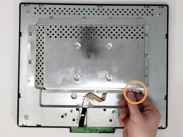
Pinch as shown, and pull towards the body to remove the cover from the stand. This will require significant force.
-
Remove the four 0.7 mm Phillips #0 screws connecting the stand to the monitor.
-
-
-
Remove the four 0.7 mm Phillips #0 screws connecting the back panel to the monitor.
-
Remove the single 0.85 mm Phillips #0 screw from the location shown.
-
Insert the plastic opening tool into the crevice along the side, top, and bottom of the monitor.
-
Pry open the monitor by running the plastic opening tool along the crevice.
-
Lift the back panel off of the monitor as shown.
-
-
-
-
Remove the two 0.7 mm Phillips #0 screws on the sides of the centerpiece motherboard cover.
-
Remove by hand the two hexagonal screws securing the digital visual interface (DVI) input.
-
The DVI is typically a blue/black connector with two built-in screw connections on either side. It is secured by hand tightening the two side screws.
-
Push the centerpiece motherboard cover toward the body to remove.
-
-
-
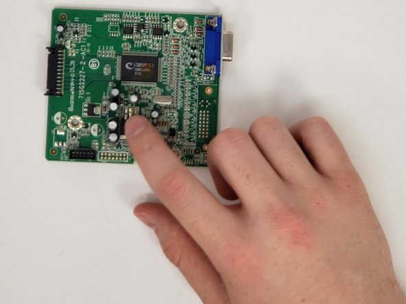
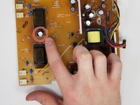
Examine the top of each capacitor to check capacitor life.
-
Replace necessary capacitors via soldering the old capacitor out and soldering a new capacitor in.
-
Refer to this soldering guide for How To Solder and Desolder Connections.
-


To reassemble your device, follow these instructions in reverse order.
Cancel: I did not complete this guide.
One other person completed this guide.
Team

University of Memphis, Team S2-G5, Baddour Spring 2019 Member of University of Memphis, Team S2-G5, Baddour Spring 2019
UM-BADDOUR-S19S2G5
3 Members
3 Guides authored