Introduction
Few notes.
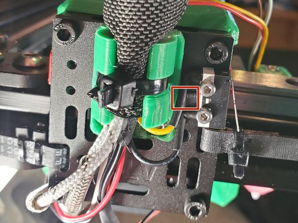
I did not modify the original wiring in anyway with the exception of the endstops. If there is a middle wire cut the wire and remove it.
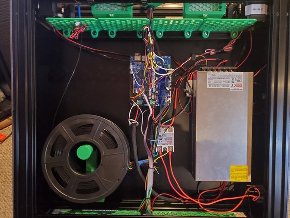
I’ve you’ve seen my previous builds you know I put a lot of effort into making things look clean. Personally I would’ve made some of the wires longer and some shorter. But with this type of kit you need the flexibility. This is the reason why the wiring isn’t clean.
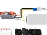
There are 3x push button switches. 1 momentary switch for power and 2x 24v latching switches. 1 of the latching switches is for the LEDs. The 2nd switch can be used for additional LEDs, fans, etc.
This is the way I did it based off the information I had and my experience. If you know of a better way or want to share some feedback feel free to contact me directly over Facebook.
What you need
Featured Document
-
-
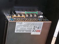
Mount the PSU with 5x M3x6 button head screws. The output voltage terminals will be facing up.
-
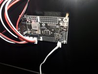
Mount the Duet by first screwing in 4 M3x6 button head screws on the inside of the printer through the back panel, into 4x M3x15mm standoffs. Mount the Duet with 4x M3x6 button head screws to the standoffs. The WiFi antenna will be facing up.
-
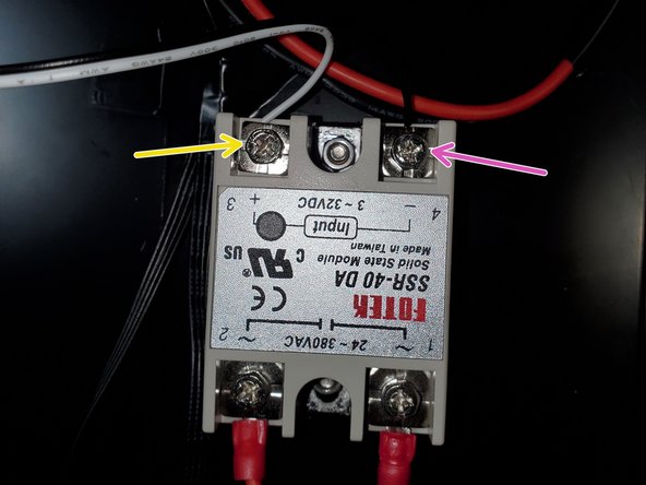
Mount the SSR with 2x M4x10 button head screws and 2x M4 nuts. The SSR will be upside down.(Terminals 3 and 4 will be facing up)
-
There wasn't really a good place to put the Wago connector for the LEDs. I used some 2 sided tape and taped it to the side of the PSU
 Ask FixBot
-
-
-
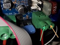
The orange arrow is the Load(AKA hot/power) wire. It connects to the Load input on the power supply and to the Load wire on the momentary power button
-
The green arrow is the Neutral wire. It connects to terminal 2 on the SSR along with the green wires of the momentary power button
-
The black wire is ground or earth. It connects to the Negative input on the power supply and the black wire of the momentary power button
-
-
-
SSR pin 3(+) > Duet pin 3 (3.3v)
-
SSR pin 4(-) > Duet PS_ON
-
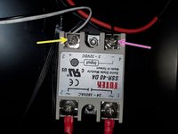
SSR pin 1 > neutral in from power plug + yellow wire from power button
-
SSR pin 2 > neutral to board + green wire from power button
-
-
-
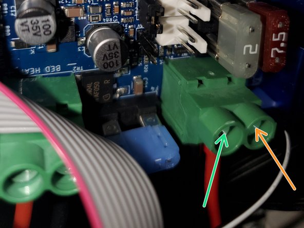
On the PSU the 3 terminals on the left(Orange) are + and the 3 on the right(Green) are -
-
Connect 1 + and 1- from the PSU output to the Duet Input paying attention to the polarity
-
-
-
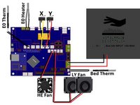
Connect the White wire to Z_PROBE_IN
-
Connect the Black wire to GND
-
Connect the Red wire to Pin 1 5v
-
Connect the Brown wire to Pin 2 GND
-
Connect the Orange wire to Pin 8 HEATER3
-
-
-
-
Connect the 10 pin ribbon cable to CONN_SD on the Duet to the Panel Due
-
-
-
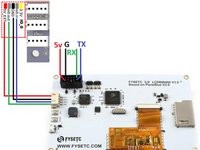
Connect the white/black wire from the NeoPixel board to the PanelDue port on the Duet
-
Connect the +/- from the NeoPixel board to the PSU output. Make sure you pay attention to polarity.
-
Connect the 3x 3 wire NeoPixel rings to the NeoPixel board
-
Connect the White(RX) wire from the BLV NeoPixel board to the TX porton the PanelDue.
-
Connect the Black(GND) wire from the BLV NeoPixel Board to the GND port on the PanelDue
-
-
-
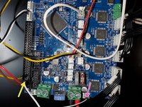
Pay attention to the Drive layout. They do not go in numerical order
-
Connect the Extruder (E0) to Drive 3
-
Connect the X stepper(Top Left stepper) to Drive 0
-
Connect the Y stepper(Top Right) to Drive 1
-
Connect the Z1 (Left Z stepper) to Drive 4
-
Connect the Z2 (Right Z stepper) to Drive 2
-
-
-
The wiring is pretty straight forward. The important thing to remember is with the Wago connectors one side is input and the other side is output. Make sure you do not cross the polarity
-
The Black wire on the push button latching switching goes to the Negative - terminal on the PSU output
-
The Yellow wire on the push button latching switch goes to the positive + side of the PSU output.
-
The Green and Red wire on the push button latching switch goes into one of the contacts on the Wago connector. This will be the Positive + side
-
The single Black wire in the kit goes from the Negative terminal on the output side of the PSU to the open contact on the same side as the Green/Red wire.
-
The both Red Positive + wires of the LEDs will go in the opposite side of the Green/Red wires
-
Both Black Negative - wires of the LEDs will go in the opposite side of the Black Negative - wire
-
-
-
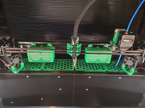
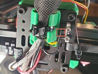
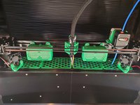
The X Carriage wiring is pretty straight forward. Polarity of E0 Therm, E0 Heater and Bed Therm is irrelevant.
-
The 2 4010 Blower fans are wired together so you only need 1 set of wires going back to the board.
-
To make the connector I soldered the 2 + wires together and the 2 - wires together. I than cut the length I needed from the original 5015 blower fan and soldered the wires together.
-
-
-
The wiring for the 24v DC bed is pretty straight forward. Make sure you pay attention to the polarity of the +/-.
-
-
-
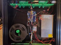
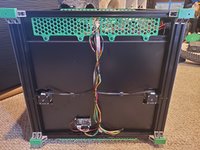
The wiring didn't turn out as well as I would've liked. Because this is supposed to be an all in one kit I didn't want to modify the wiring. After all is said and done I'll probably do some re-wiring and put in cable raceways
-
Use some small zip-ties to bundle the wires together.
-
As you can see with the back panel it's definitely not my cleanest wiring. Normally I'll make my own cables to they're the length I want.
-
-
-
Make sure your jumpers are set correctly.
-
V_FAN: This is where you select the voltage for the 5 fan ports. You want the jumper on VIN (pins 2 & 3) to set the fans to run on the voltage that is supplied to the Duet 2 WiFi(24v). If you set it to 5v(pins 1 & 2) the fans won't turn on.
-
5v Selection: You need to select if 5v is provided by the onboard regulator(24v to 5v) or from an external 5v source.
-
INT 5V EN: Most builds you will have the jumper placed here.
-
EXT 5V EN: Place a jumper here if you want to use an external PSU to provide 5v to the board.
-
Erase Jumper: Used to erase the firmware
-


Cancel: I did not complete this guide.
9 other people completed this guide.
Attached Documents
1 Guide Comment
As of Oct 2023:
In the FYSETC kit, if all components (including the Neopixel board) are updated to current versions (at the time when latest RRF is 3.4.6), then the Neopixel board cannot be connected together with the Paneldue, because then the Paneldue will not receive data (it still can send). But as delivered, the kit works as it schould.
The Neopixel board would need to be disconnected. The Neopixel board itself works fine in all cases though.