Introduction
Printed parts needed:
1x X Carriage Wire Tube Holder.stl
1x X carriage shield for the metal kit.stl
One of the following:
1x Metal kit - BLtouch adapter.stl
1x BLTouch Front Mount Adapter.stl
What you need
-
-
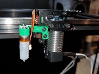
Using 2x M3x8 socket head screws mount the V6 Front Plate Mount to the front Plate.
-
Make sure it's level otherwise you will have inconsistent nozzle height.
-
Make sure the screws are tight. I've had these screws loosen up on me after 2 weeks.
 Ask FixBot
-
-
-
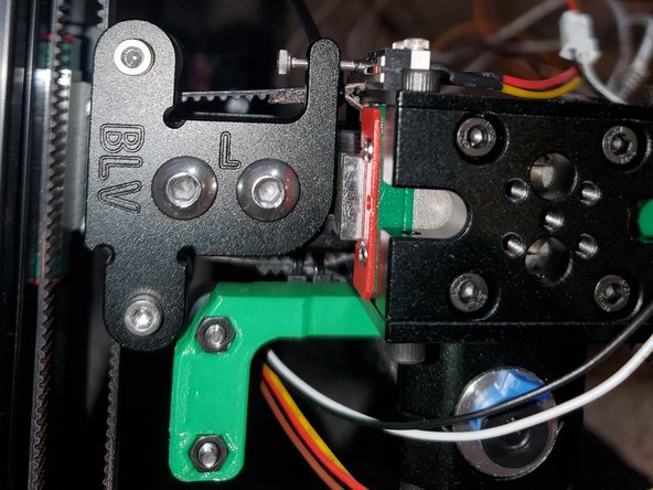
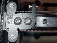
Using 2x M2 washers and 2x M2x8 button head screws mount the X Endstop on the rear late above the upper belt. Make sure the endstop lever is facing down
-
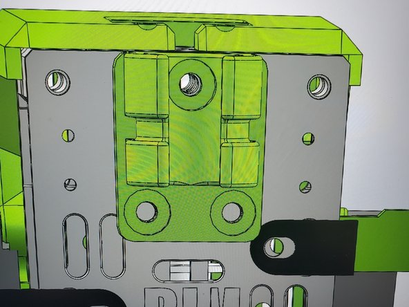
The original design has the BLTouch mounted on the rear of the carriage using 2x M3x6 button head screws to secure the mount to the Rear Plate.
-
Secure the BLTouch to the rear mount with 2x M3x8 button head screws and 2x M3 nuts
-
Secure the mount to the Front Plate with 2x M3x6 button head screws
-
Secure the BLTouch to the Front Mount with 2x M3x10 button head screws and 2x M3 nuts
-
-
-
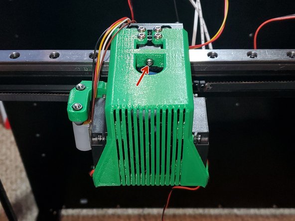
The screw needs to protrude out the opposite side enough to trigger the endstop before the BLTouch mount hits. About 2-3mm
-
-
-
-
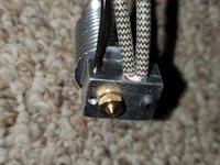
Insert the Thermistor into the heat block and tighten the small set screw
-
Insert the heater cartridge into the heat block and tighten the M3 button head screw.
-
Install the silicone sock onto the heat block.
-
Using 2x M3x16 socket head screws secure the E3D and the E3D V6 Locker to the front plate.
-
-
-
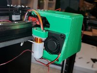
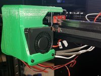
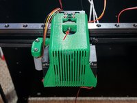
Mount the 4010 fan with the longest wire into the block shield with 4x M3x12 screws
-
Insert the 2 blowers into the side mounts and secure with 2x M2.5x6 socket head screws(top) and 2x M2.5x12 socket head screws(bottom) on both sides.
-
Secure the block shield to the X Carriage with 5x M3x8 button head screws. Don't forget about the screw on the front.
-
-
-
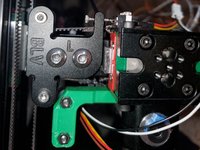
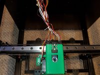
Wiring is really a personal preference but I like everything as neat as possible which is why I made a wire locker mount for the metal kit. You can find the files in the FYSETC Modified Printed Parts folder on my Github
-
Note-This will not work if you have the BLTouch on the rear of the carriage
-
Using 2x M3x6 button head screws and 1x M3x10 button head screw mount the Wire Locker to the Rear Plate
-
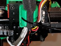
Insert the hotend wires into the wire loom.
-
If you have a 24" zip-tie insert it into the wire loom with the wires(not included with the kit). This will help keep the wire loom up
-
Using a small zip-tie, lock the wire loom into the wire locker
-
-
-
Mount the Main_Cable_Tube_Holder to the rear of the frame using 2x M5x8 button head screws and 2x M5 T-nuts
-


Cancel: I did not complete this guide.
7 other people completed this guide.