This translation was generated by a machine and has not been reviewed by a person yet. Speak this language? Review it.
Introduction
A piece of advice: take the time to read the method for performing a repair under good conditions. Browse through the two guides on the functions (step 1 to 4) and how it works (step 5 to 16). You will thus maximize your chances of success. Before studying the most common faults, one step will be dedicated to the safety precautions to take before attempting any work on this type of appliance. Then, we will look at the following steps for issues related to the power board, the control board, and the high-voltage section.
-
-
-
Microwave technology began in the 1930s, driven by a group of British researchers as part of military research.
-
In 1939, they developed the "magnetron," a device that produces ultrashort waves. This device was used to manufacture radar systems, first used during the Battle of Britain. During this research, it was noted that these waves had the effect of heating food in particular.
-
Microwave cooking was invented. The first microwave oven, branded as Radarange, was sold in 1953.
 Ask FixBot
-
-
-
Microwaves cook food in record time and offer a variety of functions that go beyond simply reheating food. Here are the main functions available. These functions make the microwave versatile and suitable for many culinary tasks, thus simplifying meal preparation.
-
Reheating: Allows you to quickly reheat leftovers or prepared dishes.
-
Cooking: Used to cook food, especially those containing water, such as vegetables, meats, and dishes with sauce.
-
Defrosting: A specific function for defrosting frozen food quickly and evenly, without cooking it.
-
Sterilization: Some models allow you to sterilize containers or utensils by using the heat generated by the microwaves.
-
Convection Cooking: Integrates a convection function to cook food more evenly by using a cooling fan to circulate hot air.
-
Grill: Allows you to brown or gratinate food by using an additional heat source.
-
Automatic Cooking: Pre-programmed settings for different types of food, such as popcorn or potatoes, which automatically adjust time and power.
-
-
-
(Fig 1) A microwave oven contains a microwave transmitter called a "magnetron." The emitted waves are confined within an enclosure called a cavity. This cavity is closed by a door (Rep 1) coupled with a safety device (Rep 8) to prevent the emission of waves to the outside.
-
The door is equipped with a metal screen pierced with small-diameter holes: this creates the analogue of a Faraday cage, which prevents waves from passing through while still allowing the inside to be seen. To make the oven airtight, the door is equipped with a seal strip that completes the seal.
-
A wave stirrer and/or a turntable (Rep 2) helps distribute the waves better over the food. The latter is driven by a motor (Rep 9) and placed on a rotating ring (Rep 11).
-
A power supply system is connected to the socket (Rep 6) and a control panel (Rep 7) allows for the selection of cooking time and power.
-
Depending on the type of device, the control panel consists of rotary knobs that allow the cooking power and duration to be selected. It also has a push button for opening the door. These are generally mechanical or electromechanical ovens (Fig 2). They are simple and economical.
-
Multi-function microwave ovens (Fig 3) are electronic and equipped with control panels with an electronic display, program selection keypad, memory, etc...
-
A mica protection plate is placed at the exit of the microwave tunnel (Rep 4) generated by the magnetron. A lamp (Rep 5) illuminates the cavity when the door is opened.
-
Some devices have an upper (Rep 3) and/or lower (Rep 10) grill. We will not study this functionality, which could be the subject of a specific study.
-
-
-
Unlike a conventional oven, a microwave does not have a temperature setting and therefore no thermostat; the only existing settings are power and operating time, which must be set blindly based on your own experience or the manufacturer's instructions.
-
Fig 1 This is an example of a control panel found on mechanical devices. Operation is very simple. 1-Turn the power knob to set the microwave power to the desired value. 2 - Turn the timer knob to set the recommended cooking time.
-
3 - After setting the power and duration, the microwave oven begins cooking. 4 - When the cooking time is reached, a "ding" sounds and the device stops.
-
Fig 2 This is an example of a control panel found on electronic devices. Reading the user manual is required to use the various features of this type of device.
-
-
-
-
-
What is the cooking of a food? It is its chemical transformation through heat.
-
Cooking allows for modifying the taste, flavor, appearance, color, texture, volume, weight, or nutritional qualities of food. It modifies its chemical and physical structure and can thus make it digestible, nourishing, or tastier, and sometimes eliminates toxicity.
-
Exposing food to a heat source (fire, heat from an electric resistance…) will trigger reactions between its components. For instance, the Maillard reaction consists of an interaction between sugars and proteins, which gives your roast its taste!
-
But what is heat, from a physics point of view? It is the level of agitation of molecules or atoms… A completely immobile molecule has a temperature equivalent to absolute zero, that is to say minus 273°C! Whereas the dioxygen molecules that float in a house wiggle at about 500 meters per second.
-
A microwave oven, or more simply a microwave, is a household appliance used mainly for heating and quick cooking of food, by the agitation of the water molecules they contain, under the effect of microwave radiation.
-
-
-
Microwaves are a type of wave located between radio waves and infrared radiation on the electromagnetic spectrum. In the case of microwave ovens, the wave frequency commonly used is approximately 2,450 megahertz (2.45 gigahertz).
-
The electromagnetic field (2450 MHz) creates intense agitation of water molecules, which oscillate as microwaves pass through. Heat is generated by the friction of water molecules against one another. This thermal effect is therefore the result of the interaction between microwaves and water molecules.
-
The penetration of microwaves into food items is linked to the power of the emitter. The direct thermal action is very intense at the surface and in the first few layers. Penetration gradually decreases with thickness.
-
These waves also possess another interesting property: they are not absorbed by most plastics, glass, or ceramics. Metal reflects microwaves, which explains why metal pans do not work well in a microwave oven.
-
This is also the reason why these appliances have metal walls, for reflection.
-
-
-
Fig 1 The diagram helps to understand how the electromechanical ovens used by most manufacturers work, with the exception of a few options such as combination ovens or grill functions, which include additional heating elements.
-
The electrical circuit consists of 3 parts: the power supply board Fig 2 connected to the socket. It is a small input electronic board equipped with a fuse and a few filtering components; this is the oven's main power supply.
-
The power supply then passes through a series of safety systems: device overheating and door. The circuit also powers a lamp that illuminates the cavity, the motor that drives the turntable, the cooling fan motor for the magnetron, and the control board used to operate the device. Fig 3
-
Once filtered and secured, the power supply is connected to the high voltage. This is the third part, composed of a transformer, a capacitor, and a diode, which are connected to the magnetron, the central component of the device.
-
-
-
The electromechanical timer allows you to select the duration and cooking modes. It consists of a micro motor and 2 mechanical systems. A cam system manages the power regulator contact. A gear system manages the cooking duration contact.
-
The micro motor is a synchronous motor powered by 230V. The winding resistance is on the order of several kΩ.
-
-
-
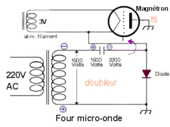
The power circuit consists of a three-winding transformer (230V / HV – LV). The secondary of the transformer delivers 1600 Volts, which is necessary for creating the electric field. It consists of a very high number of turns. A voltage multiplier transforms this voltage into a 3200V voltage.
-
The magnetron is the microwave generator. To function, it requires a current of 700 milliamperes at -3200V relative to ground. Our transformer produces 1600V; it is sufficient to double the voltage using a classic electronic circuit: a Latour doubler, also known as a Schenkel doubler.
-
To double the voltage, the high voltage from the transformer is sent into a capacitor. At the output of the capacitor, there is a diode. There is also, and now almost systematically, a fuse on the high voltage circuit.
-
A second winding powers the magnetron filament at a very low voltage of 3.2 V, but with a current of around 10 amperes.
-
-
-
This consists of a cylindrical anode, or anode block. Electrons move from the cathode toward this anode, but due to the presence of magnets, a cloud of rotating electrons is formed.
-
The charges then interact with the resonant cavities, oscillations that reverberate on adjacent vanes, creating a very high-frequency magnetic field (2,450 MHz, or 2.45 billion oscillations per second). An antenna is placed at the top, which collects the magnetic field and sends it toward the waveguide.
-
The waves are brought to a stirrer, a wave fan, which projects them inside the oven. That is when they penetrate the food, or bounce off the walls and are reflected back toward the food.
-
Cooking power regulation: It is not possible to modulate the emission power of the magnetron. To vary the cooking power, the magnetron's operating time is adjusted.
-
Example: Minimum power (defrosting) ⇒ 10 seconds (every 30 seconds) Medium power (gentle cooking) ⇒ 20 seconds (every 30 seconds) Maximum power (high cooking) ⇒ 30 seconds (every 30 seconds)
-
-
-
-
An electrical transformer is a converter that allows you to change the voltage and current intensity values delivered by an alternating electrical power source into a system of voltage and current with different values but the same frequency and form. It performs this transformation with excellent efficiency.
-
In a static transformer, energy is transferred from the primary to the secondary via the magnetic circuit formed by the transformer's core.
-
In the event that all losses and flux leakages are neglected, the ratio of the number of turns in the primary and secondary completely determines the transformation ratio of the transformer: U2/U1=N2/N1 U1=primary voltage U2=secondary voltage N1= number of primary turns N2= number of secondary turns
-
The microwave transformer is a high-voltage transformer. It is used as a step-up transformer. It serves to provide high voltage to the magnetron. It consists of 3 windings: the primary winding powered at 230V, and two secondary windings providing 3.2V and 2100V.
-
3.2 volts are necessary for powering the cathode. The winding is of large diameter because the intensity exceeds 10A.
-
2100 volts are necessary to create the pulsed voltage between the anode and the cathode of the magnetron. The HV winding is of very small diameter because it only generates a weak current. One end of this winding is connected directly to the device's ground.
-
-
-
The capacitor acts as a voltage doubler. It doubles the 1600V voltage from the secondary of the transformer to approximately 3200V.
-
This non-polarized capacitor is built around a capacitance between 0.95 and 1.15 microfarads that stores electrical energy during a half-cycle, and a 10MΩ internal resistance that ensures its discharge.
-
When the device is powered off, it is possible to have a voltage close to 4000 volts at its terminals. Even if it includes a discharge resistor and despite working with the power disconnected, it is ABSOLUTELY NECESSARY to discharge the capacitor before working on the other components of the oven.
-
To do this, you can use a 1MΩ resistor to short-circuit the terminals of the capacitor. You can also use needle-nose pliers after waiting about ten minutes after having unplugged it from the mains socket.
-
-
-
The function of a diode is to rectify alternating current into direct current.
-
A diode allows current to pass in only one direction. There are several possible solutions for rectifying current. The one chosen to power the magnetron is a circuit with a single diode that powers the magnetron every other half-cycle (the positive half-cycle is conductive, the other half-cycle is blocked).
-
Fig 1 During the half-cycle where the diode is non-conductive, a high-voltage capacitor is charged, which will then discharge during the half-cycle where the diode is conductive. The capacitor's voltage will add to that of the transformer to obtain the 4000 V voltage required to power the magnetron.
-
The capacitor & diode assembly is called a voltage doubler because it allows the 2700 V alternating voltage from the transformer to be brought up to a 4000 V direct voltage.
-
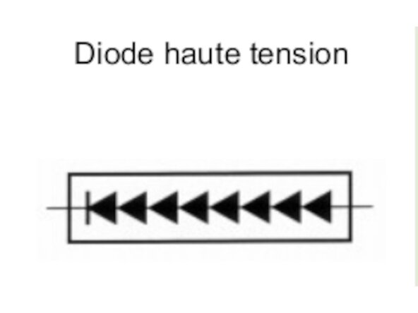
The high-voltage diode is designed for a peak reverse voltage (Vr) on the order of 6000 volts. To withstand such a voltage, a simple PN junction is not enough. Several junctions must be stacked in series. The power diode is therefore a stack of eight diodes Fig 2.
-
Due to this stacking, the HV diode cannot be checked using an ohmmeter.
-
-
-
This is an optional component. It is mounted in parallel with the capacitor Fig 1. It consists of two back-to-back diodes with reverse breakdown voltages VD1 = 6000 Volts, VD2 = 1200 Volts Fig 2. It serves to protect the transformer in the event of a power diode short circuit.
-
The goal is to create a clean short circuit that will blow the primary fuse. If the HV diode shorts, the capacitor finds itself in parallel with the HV secondary winding. This results in the equivalent schematics Fig 3.
-
The voltage delivered is an alternating periodic voltage with a value of 3000 Volts max. Diode D2 breaks down and shorts. The current in D1 is too high and D1 also shorts. The secondary winding is short-circuited. An overcurrent occurs at the secondary, then at the primary.
-
This overcurrent is such that the primary fuse blows. The transformer is protected.
-
-
-
Fig 1 "Klixon" thermal switches. These are installed on the magnetron and the oven cavity. When the temperature exceeds the standards, the switches cut the power supply, thus protecting against excessive overheating incidents.
-
Fig 2 In most cases, the microwave fuse is equipped with a spring in its structure. The fuse is made of fusible wire designed to withstand slow melting at a few hundred milliamperes (between 500 and 700 mA).
-
The operation must happen very quickly to prevent an electric arc from forming. The spring is under mechanical tension. It is stretched. When the fusible wire melts, it returns to its original position, quickly separating the entry and exit points of the electric arc, blowing out the arc, just like blowing out a candle!
-
This fuse is placed in a colored plastic insulating casing, usually red.
-
Fig 3 The microwave oven is equipped with a door safety assembly. These door contacts, known as micro-switches, are there to protect the user from potential burns or injuries that the microwave generator would cause if the door remained open.
-
When nothing is pressing on it, it is at rest. A micro-switch has three terminals. One terminal is the common (terminal 1), where the current "arrives." Opposite it, a type of switch! One contact closed at rest (terminal 2) and another open at rest (terminal 4).
-
When the switch is pressed, the states reverse: contact 2 opens and contact 4 closes.
-
-
-
Fig 1 Turntable motor: it is used to rotate dishes to evenly distribute heat in the food being heated.
-
On some oven models, the turntable drive motor is powered by the cooling fan motor with 30 volts AC! It is remarkable that on some cooling fan models, there are three connectors: a live wire, a neutral wire, and the third shows a voltage of about thirty volts when measured.
-
This intermediate voltage is taken from the coil of the cooling fan motor. It therefore acts both as a cooling fan and as an autotransformer to power the turntable motor.
-
Fig 2 Cooling fan: it allows for: - Cooling the magnetron and the transformer - Renewing the air in the cavity to prevent condensation - Driving the wave stirrer (stirrer) in some cases. The motor is of the asynchronous type. The resistance of the winding is on the order of a hundred Ω.
-
-
-
-
-
A microwave oven is not a harmless appliance: under the oven cover is a high-voltage generator capable of killing. Before any technical intervention, unplug the oven as you must do for any repair and any appliance, and always keep the plug that connects to the power socket in sight.
-
Leave the oven unplugged for about ten minutes, then remove the cover. Generally, 5 or 6 screws located at the rear hold it to the frame Fig 2. When the high-voltage circuit is visible, short-circuit the capacitor of the high-voltage circuit using insulated pliers Fig 3. Use good insulated pliers!
-
You must NEVER attempt to take a measurement or perform any other intervention when the cover is removed and the oven is powered on and/or without having discharged the capacitor. This is likely to be charged with over 3000V.
-
All checks on the high-voltage section are performed statically, with the oven unplugged and the capacitor discharged, by following the procedure below. A simple multimeter is sufficient to identify 95% of electrical faults.
-
Here is a tip to perform tests while avoiding risks associated with the High-Voltage section. Simply disconnect the 2 wires that power the primary of the HV transformer and insulate them. This allows the power supply and control sections to be tested under 230VAC, which can be done safely.
-
Once these 2 sections have been verified, it will then be possible to check the various HV components while remaining powered off. It is only when all tests and measurements are completed that you can reconnect the wires to the transformer primary and verify that the oven is working properly after replacing the device cover.
-
-
-
The electronic board is equipped with a medium-voltage glass fuse. This fuse may be blown. To check it, you must test it with a multimeter. It should indicate a value close to 0 ohm Fig 1.
-
Recall that the fuse is a safety component whose role is to open an electrical circuit when the electrical current in it reaches, or exceeds, a given intensity value for a certain amount of time. This value is indicated on the fuse itself. In the case of a glass fuse, the rating is indicated on the ferrule.
-
The fuse rating is between 3.15 and 15A. If it has blown, it must be replaced with one of the identical rating. You must also choose the fuse type: F (fast-acting) from 1 to 10 ms or T (time-delay) from 10 to 100 ms. This type also appears on the ferrule following the rating Fig 2.
-
This power supply board, intended mainly to filter interference on the electrical network, generally does not present any other problems.
-
The blowing of the fuse may be due to two types of problems. Either it is a fault in the control circuit, or the fault originates from the HV section. We will see how to find the source of the problem in the following steps.
-
As seen in the step dedicated to safety, simply unplug the transformer's primary to perform the tests safely. This way, you will be able to test the power supply connected only to the control circuit.
-
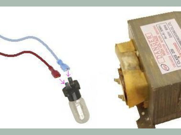
To facilitate the test, it is possible to connect the wires that arrive at the transformer's primary to a 220V light bulb Fig 3. You can also connect a multimeter.
-
Plug the oven back into the mains, set it to full power, and turn it on. If the lamp does not light up, you are facing a failure of the control circuit. If the lamp lights up, the failure is in the high-voltage circuit.
-
-
-
One of the problems that can occur in the control circuit comes from the "door safety" microswitches and the mechanical device that activates them. There are 3 microswitches: a primary one SW1, a secondary one SW2, and a control one SW3. SW1 and SW2 are activated via the door and interrupt the microwave emission.
-
They also prevent the appliance from operating when the door is open. One of the two is completely inaccessible to the user, so as to prevent the oven from operating by inserting an object into the door latches.
-
The third microswitch only reacts in the event of a failure of the first two by short-circuiting the power supply to take the oven out of service.
-
SW1 controls the proper closing of the door. SW2 authorizes the oven to operate Fig 2. SW3 causes the fuse to blow in the event of a failure of the primary microswitch SW1.
-
Indeed, we can see that if SW1 closes and at the same time SW3 remains in position, it causes a short circuit between phase (L) and neutral (N), which leads to the breaking of the fuse. Fig 3
-
Fig 1 shows the position of the cams that press on the microswitches depending on whether the door is open or closed. The attached table also displays the ohmic value of each contact as a function of the door position.
-
-
-
If there is no 230V power at the primary of the HV transformer (test bulb off), one of the control circuit thermal safety switches may be faulty. These are the thermal cutouts (klixons) located on both the magnetron and the oven cavity. Fig 1
-
When the temperature exceeds the standard limits, the switches cut off the power supply, thus protecting the device against incidents of excessive device overheating.
-
To test them, simply measure their ohmic value. It should be close to zero during normal operation. If the value is "infinite," the component is faulty. It must be replaced with an equivalent model. To find the maximum temperature rating it is set for, simply read it on its front face.
-
During reassembly, it is recommended to reinstall the thermal cutout with thermal paste between its front surface and the metal surface to which it is screwed.
-
Fig 2 The ovens are equipped with a light bulb that illuminates the cavity. It is a filament bulb powered by 230VAC. This bulb can burn out. Simply replace it with an equivalent one. There are several types of bases depending on the manufacturer.
-
Fig 3 To rotate the turntable, the ovens are equipped with a synchronous motor placed below the tray. This is powered either by 30VAC via the fan motor or by 230VAC. If the tray no longer rotates, measure the motor's supply voltage with a multimeter. If the voltage is correct, the motor is faulty.
-
To perform this measurement, locate the wires powering the motor, connect the multimeter to them, and start the microwave (with the transformer primary disconnected).
-
To proceed with replacing the motor, some ovens are equipped with a hatch that can be opened by removing a few screws, or by using flush cutters to snip the ties on the bottom panel's protective grille. If this is not the case, you must disassemble the device's frame.
-
-
-
Fig 1 - Electromechanical control This type of control is used on older ovens. A timer is used to manage cooking modes and times. The failure can present in two ways.
-
Either the timer refuses to work. The oven does not start.
-
Or the microwave heats, but the time does not count down, the clock motor is cut off, or a contact is broken in the mechanism. As a result, the oven heats, but never stops. This sub-assembly is difficult to disassemble/troubleshoot. In both cases, you must replace the entire control unit.
-
Fig 2 - Electronic control These are found in more recent ovens. Each manufacturer designs its own control boards, which vary in sophistication. It is not possible to provide guidelines for their repair.
-
You must proceed by elimination to determine whether the board is at fault or one of the other components that make up the oven.
-
-
-
Before performing any work on high voltage components: Remove the cover. Discharge the capacitor using insulated pliers. Identify then unplug the primary transformer conductors. The High Voltage must no longer be powered
-
Fig 1 Locate the primary winding. This is the one that was unplugged. It is powered by 230V. It is made of medium-gauge wire. Use an ohmmeter to measure the winding resistance. It should be close to 3 ohms.
-
Fig 2 Locate the low voltage secondary winding: It delivers a low voltage of 3.2 Volts required to power the magnetron filament. It is made of 2 to 3 turns of heavy-gauge wire. The current exceeds 10A. Use an ohmmeter to measure the winding resistance. It should be close to 1 ohm.
-
Fig 3 Locate the high voltage secondary winding: It delivers a high voltage of 2100 Volts required to create the electric field. It consists of a very high number of turns of very thin wire. One end of this winding is connected directly to the transformer chassis (which is itself connected to ground).
-
Use an ohmmeter to measure the winding resistance: It should be between 50 and 230 ohms.
-
-
-
This measurement is optional. It is used to check the characteristics of the HV transformer. The transformer is disassembled and is outside the device. This test will be performed on a workbench. WARNING DANGER: Identify the High Voltage secondary winding. Never power the primary of the transformer. Use hook clips.
-
Measure the mains voltage. Apply the mains voltage to the High Voltage winding. Place a voltmeter on the primary, then on the low voltage secondary. Record these voltages, then calculate and verify the transformation ratios.
-
rt1= V2HTr.m.s. / V1r.m.s.≈ 10
-
rt2= V2LTr.m.s. / V1r.m.s. ≈ 0.014
-
-
-
Fig 1 Static check of the power diode: The HV diode cannot be checked with a standard ohmmeter. Therefore, you only verify with the ohmmeter that the diode is not short-circuited. Measure the diode's insulation resistance with the ohmmeter: it must be infinite.
-
Fig 2 Dynamic check of the power diode The diode is removed; it is outside the device. This check will be performed on a bench. Since the diode's threshold is around 9 volts, you must create a setup with batteries to provide a voltage of at least 12V up to 18V.
-
These are placed in series with a 6V/12W or 12V/25W bulb depending on the applied voltage and the diode. In the diode's forward direction, the lamp lights up. In the reverse direction, it remains off. If the lamp does not light up, the diode is defective.
-
Another method allows you to test the operation of the diode. You must use alligator clips and a 230vAC bulb. WARNING DANGER This test is performed live, so connections must be made while powered off, and a socket equipped with a switch must be used to avoid any risk of electrocution.
-
You must place the diode in series with the bulb (the orientation of the diode does not matter). To do this, you must unplug it from the control circuit and connect it to the socket with the diode in series using alligator clips Fig 3
-
If the diode is OK, it conducts during one half-cycle, but it is blocked during the other half-cycle. The bulb therefore glows dimly. If it remains off, it is dead.
-
-
-
Use an ohmmeter to measure the insulation resistance of the AK protector in both directions. It must be infinite in both directions. If there is continuity in either direction, the AK protector is faulty.
-
Warning. The AK protector must be connected to the capacitor terminals in the correct orientation. Incorrect connection can cause a short circuit of the component and blow the primary fuse.
-
-
-
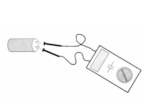
Fig 1 Static capacitor test: With a capacitance meter: Measure the value of the capacitor and compare it with the value given on the component. (≈ 1 μF)
-
With an ohmmeter: This is an approximate method. Set the ohmmeter to the highest range (2 MΩ). Apply the two probes to the two terminals of the capacitor: The value will rise toward infinity. Quickly reverse the two probes: The value will drop and then rise toward infinity.
-
Dynamic capacitor test. Optional This uses the capacitor's impedance. If an alternating voltage is applied to the capacitor, we use the relationship U = Zc × I, where Zc is the capacitor's impedance.
-
It is defined by the relationship: Zc= U/I = 1/C.w = 1/C.2π.f. U is expressed in Volts, I in Amperes, C in Farads, f in Hertz, and Z in Ohms. If a capacitor is powered by 230V / 50 Hz mains voltage, the capacitor can be calculated as follows:
-
C= I/U.w = I/U.2π.f = I/230.2π.50 = I/23000.π= I/72260
-
WARNING DANGER This test is performed while live, so it is necessary to make the connections while the power is off and to use a socket equipped with a switch to avoid any risk of electrocution.
-
Use wire grabbers and set up the circuit as shown in Fig 3. To do this, you must have two multimeters. Measure the mains voltage. Apply the mains voltage to the capacitor. Measure the current intensity with a milliammeter in AC mode. Calculate and verify the capacitor's value.
-
Example: U = 230 V C = 1μF I = 72.2 mA
-
-
-
Fig 1 Measure the filament resistance with an ohmmeter. The value should be close to 0.5 ohm.
-
Fig 2 Measure the insulation resistance between the anode (ground) and the cathode (one of the filament terminals) with an ohmmeter. The value should be infinite.
-
Fig 3 Verify the presence of the metal seal strip to prevent wave leakage during reassembly. Check for any signs of arcing on the antenna.
-
-
-
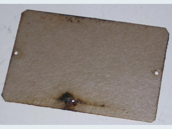
Sparks may occur inside the device's cavity. Replacing the mica plate and cleaning/degreasing the parts behind it will be necessary. Mica can be purchased at retail, and it can be cut to match the shape of the original.
-
It protects the magnetron antenna from splashes, which can be affected over time; this is why it is important to clean the cavity regularly, using clear water if possible.
-
-














That's it! After having studied the functionalities in the first two microwave oven guides, and then the different sub-assemblies that compose it, we have just reviewed the main causes of failure for this appliance.
We hope this has allowed you to learn more about your device and thus be capable of repairing it yourself.
If you liked it (or not!), do not hesitate to leave us a comment. And if you are in the area of 'Atelier Soudé, come see us. We organize co-repair workshops, popularization sessions, and lots of other things….
Cancel: I did not complete this guide.
3 other people completed this guide.

