Introduction
The aim here is to see the various components that make up the device, to understand what they are intended for, how they work independently and also how they interact with each other.
-
-
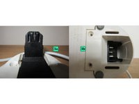
The principles are simple. The base is connected to the mains via the power cord. When the reservoir is placed on the base, the 3a 3b device powers the resistor at the bottom of the reservoir. A 6 switch on the reservoir handle switches the power on and off.
 Ask FixBot
-
-
-
-
The reservoir consists of a plastic shell with a handle. Inside this handle is a 6 switch for switching on the kettle. The resistor 4 placed inside, is fixed by three screws to the connection device 3b A gasket 5 ensures watertightness.
-
The 6 switch is connected to the 3b device located at the bottom of the reservoir, by a plastic rod which, by translation, activates an electrical contact system.
-
-
-
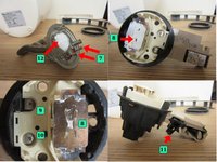
The 3 device is the centerpiece of this kettle. It performs a number of functions: - electrical connection between the base and the reservoir - manual switching on and off of the heating element - automatic switching off when the water temperature is reached.
-
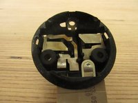
It consists of 2 parts. One, placed on the base 3a, the other placed at the base of the tank, 3b. The latter performs all 3 functions. It is made up of a system of metal fins which are activated to make electrical contact.
-
The resistor has two 7 terminals mounted on a 12 metal support. Part 3 is made of metal fins. The 9 and 10 blades come into contact with the 7 resistor terminals. The 8 blade comes into contact with the 12 support.
-
The ON/OFF switch 11 is located on top of part 3.
-
When this button is switched on, the 9 blade is activated, allowing current to flow between the socket in the base and one of the 7 terminals on the resistor.
-
The 10 reed is normally closed (the water is cold), so the current can pass through and feed the resistor, which starts to heat. When the temperature is reached, the 8 reed deforms and opens the circuit by toggling the 11 switch. The resistor stops heating. The M/A button 6 returns to its position at the stop.
-


Now that we know the functions of our appliance and are familiar with its subassemblies and operation, we can move on to the repair phase with the following tuto: "Kettles - Common breakdowns"
Cancel: I did not complete this guide.
2 other people completed this guide.
Special thanks to these translators:
100%

shingle is helping us fix the world! Want to contribute?
Start translating ›

Team
