Introduction
I encourage you to study the frame drawing so you have a good idea of how the frame is supposed to be assembled. It would also be wise to print out the frame dimensions and label the extrusions with the length to make assembly easier.
Use good quality Allen/hex wrenches. I prefer to use Allen/hex bits in a socket because it helps prevent rounding the heads
Printed parts needed:
2x 2040_Jig.stl
2x 2020_Jig.stl
What you need
Featured Document
-
-
Take 2 560mm and 1 496mm 2040 extrusions. Make sure you pay attention to where the holes are on the sides of the extrusions for the M6 screws that are part of the blind joint mounting.
-
Thread 4x M6x16mm button head screws into the threaded holes on the end of the 496mm 2040 extrusion so there's a gap of about 2-3mm.
 Ask FixBot
-
-
-
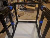
Slide the 496mm 2040 extrusion into the channels of both 560mm 2040 extrusion. The 2 holes on the 20mm side that are closest to the top of the 560mm 2040 will be for the top of the frame. The top of 496mm and the 560mm 2040 should be flush.
-
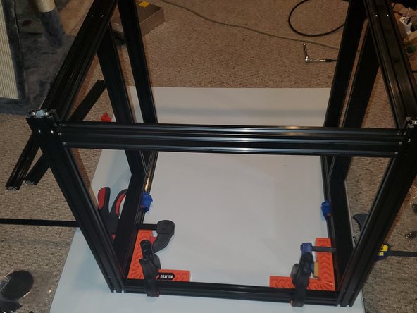
Using your corner clamps, clamp both 560mm 2040 and the 496mm 2040. Tighten the M6 button head screws.
-
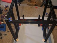
Remove the corner and clamps. Double check to make sure that after you remove the clamps the extrusions are still square.
-
Do this for both the left and the right sides
-
Note: The work space I had wasn't ideal. The extra extrusion piece was used to make sure the joints would be flush.
-
-
-
It's best to leave the MGN carriage on the rail to prevent any of the 3/32" ball bearings from falling out. Also leave the red stoppers on the ends to prevent the carriage from actually falling off.
-
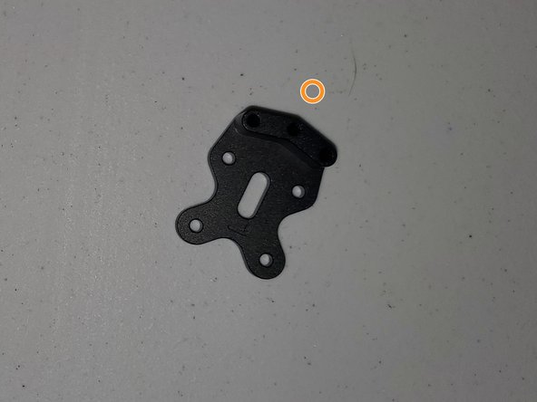
Using 4x M3x8 socket head screws mount the LEFT Y MGN mount to the MGN carriage paying attention to the L and the R on the plate.
-
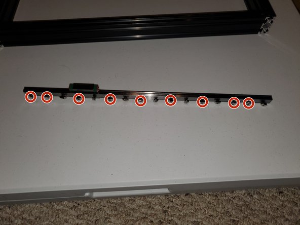
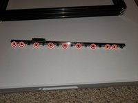
Using 9x M3x8 socket head screws and 9x M3 T-Nuts drop the M3x8 screws into the holes of one of the 400mm linear rails. Now remove the 2 red stoppers making sure the carriage doesn't slide off the rail. Thread the M3x8 screws into the T-nuts enough so they don't fall off.
-
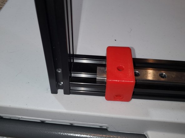
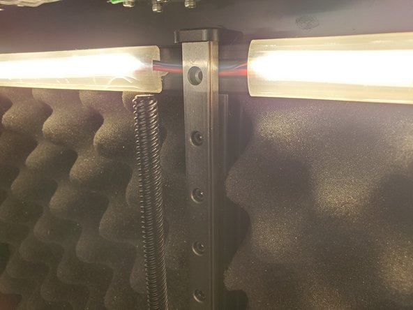
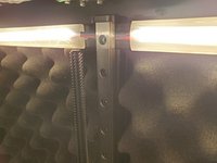
When you get to where the MGN carriage is, slide it out of the way to get to those holes. Line up the linear rail so the T-nuts drop into the inside channel of the 2040. Using the picture attached as a reference
-
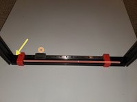
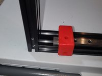
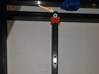
Attach 1x 2040 linear rail placement guide at each end of the rail. Keeping the same orientation as the picture with the linear rail in the channel farthest away from you, set the gap from the inside edge of the 2040 to the linear rail to 25mm.(Yellow arrow).
-
Since this is for the left side the Y MGN mount should have a L on it. The linear rail should be in the channel farthest away from you and the 25mm gap should be to your left
-
Tighten the screws roughly 1/4 to 1/2 turn working your way down the rail. Remove the placement guides
-
-
-
Repeat the same steps for the right side using the Y MGN mount with the R on it except the linear rail will go in the channel closest to you
-
-
-
-
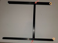
Take 4x 6x16mm button head screws and thread them into the threaded center holes of the 442mm 2040 leaving 2-3mm of head clearance.
-
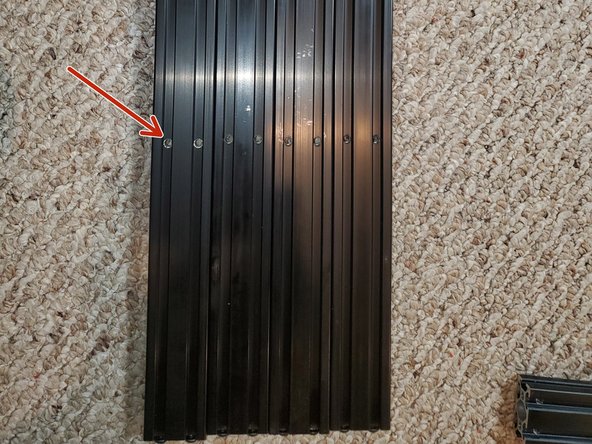
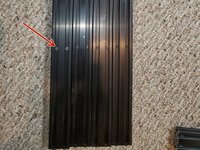
Take 2 496mm 2040 with the holes drilled along the channel. Slide the 442mm 2040 into the extrusion lining up the heads of the button head screws with the holes along the face(red arrow). Do not tighten the screws all the way.
-
Once you have the 2x 496mm 2040+442mm 2040 assembled thread 8x 6x16mm button head screws into the threaded holes of the 496mm 2040 leaving 2-3mm of gap
-
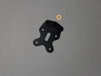
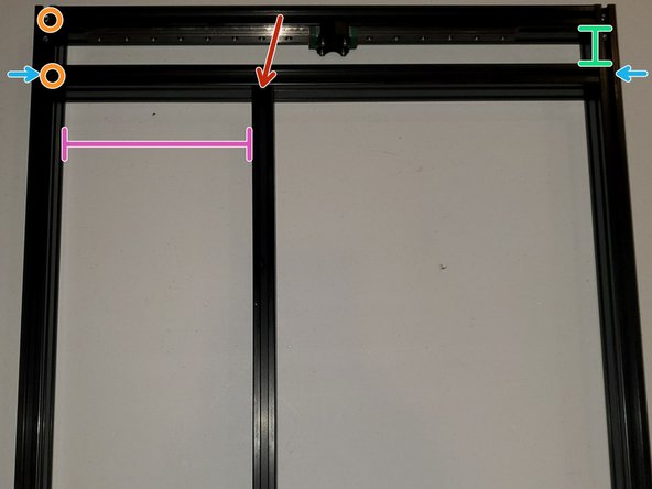
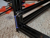
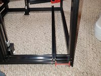
Using the picture as a reference, slide the 2x 296mm 2040+442mm 2040 assembly into the partial left side frame from step 4. The orange circles will go towards the front of the printer(same corner that had the 25mm gap for the linear rail).
-
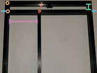
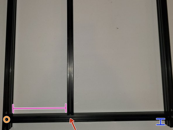
Set the gap from the underside of the top 496mm 2040 to the 496mm 2040 directly on top of the 442mm 2040 to 36.8. When the gap is straight and at 36.8mm tighten the 4x M6x16mm button head screws(blue arrows)
-
The gap for the purple line should be 178.8mm(you can use the jig provided in the download). Tighten down the top 2x M6x16mm button head screws(red arrow).
-
-
-
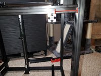
With the top of the 442mm 2040 tight we need to do the same thing to the bottom.
-
The blue line should be about 20.2mm. Once your gap is set at the bottom of the 496mm 2040 snug the 4x m6x16mm screws tight enough so the 2040 doesn't move.
-
Set the gap for the purple line to 178.8mm and tighten the 2x M6x16mm for the 442mm 2040 on the bottom face of the 496mm 2040.
-
Double check the measurements on the bottom(blue) are still about 20.2mm on both sides. Once both are equal tighten the 4x M6x16mm for the bottom 496mm 2040 so they're fully tight.
-
-
-
Assemble the right side in the same manor you did the left.
-
Orange to identify the front corner where the linear rail gap is 25mm
-
Purple line = 178.8
-
-
-
Both Left and Right sides are assembled. The orange circle shows the front corner for the right side.
-
I used blue masking tape to secure the MGN carriage to the frame so they wouldn't slide during assembly.
-
-
-
The following steps are the same for both the left and the right side
-
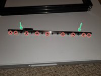
Take 1 400mm linear rail. Insert 9x M3x8 socket head screws into the holes. Do not put a screw in the top hole(blue circle)
-
Thread 9x M3 T-nuts onto the M3x8 screws enough so they won't fall off.
-
Align the linear rail so the T-nuts drop into the channel on the 20mm face of the 442mm 2040.
-
The top of the linear rail should be flush with the face of the 496mm 2040. Using 2 2020 linear rail guides, start at the top and work your way down the linear rail tightening the M3 screws so they're snug
-
Once all M3x8 screws are snug go back and tighten them 1/4-1/2 turn to tighten them completely.
-
Once again be mindful of the MGN carriage. You don't want the carriage to slide off the rail during assembly. To secure the MGN carriage you can wrap masking tape around the MGN carriage and the frame
-
-
-
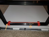
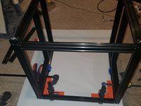
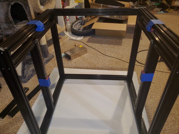
The main picture is of the assembled frame upside down with the front opening closest to you
-
Take the 3x remaining 496mm 2040 and thread 12x M6x16 button head screws into the threaded holes leaving 2-3mm of head clearance.
-
Identify the front corners. Along the front there will only be 1x 496mm 2040 along the bottom of the front of the printer
-
Using your corner jigs clamp the left side, right side and cross supports together.
-
To make it easier because I was doing the cross beam for the back top first I slid the 496mm 2040 that was for the front bottom to the front top(where the orange circles are) and tightened the button head screws.
-
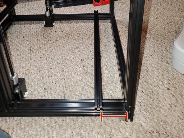
Once the back top was done I tightened the back bottom. The 496mm 2040 should be 20.2mm from the edge(blue line)
-
With the back complete, loosen the 496mm 2040 cross support and move it from the front top to front bottom. Make sure the blue line gap is 20.2mm. When everything is square and the dimensions are correct tighten down the 4 button head screws
-
-
-
Take one of the 576mm 2020 extrusions and insert 4x M5x8 button head screws. Thread on 4x M5 T-nuts enough so they don't fall off.
-
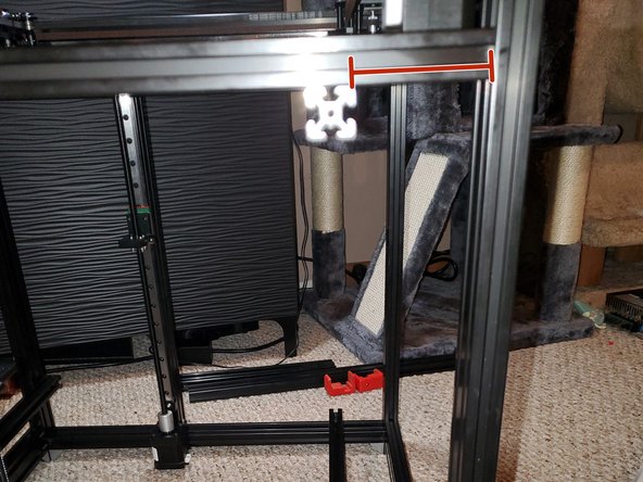
Insert the T-nuts into the channels on the back face of the front of the picture. The distance from the bottom of the 2020 to the top of the 2040 should be 45mm(blue line)
-
Take another 576mm 2020 extrusions and insert 4x M5x8 button head screws. Thread on 4x M5 T-nuts enough so they don't fall off.
-
Insert the T-nuts into the channels on the top face of the bottom 496mm 2040. The distance from the back of the 2020 to the front of the 2040 should be 60mm(blue line)
-
Repeat the previous 2 steps to add the cross support to the top
-
-
-
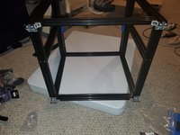
Here you see the frame rotated so the back is on the table.
-
Secure 12x external corner brackets with 24x M5x8 Button Head screws and 24x M5 T-nuts to the bottom of the frame
-


I wasn’t paid to write these guides. Ben asked me to do it as a favor to him. Considering all that he’s done for our community I felt it was the least I could do. To be honest even though it took about 2 months to build and document, I had a lot of fun doing it. It forced me to write guides in a manner that was easy for everyone to understand and cleanup my Github so I could share any files that were used that aren’t part of the original download. You’re not obligated but if you would like, feel free to donate.
Cancel: I did not complete this guide.
14 other people completed this guide.