Get answers from this document
We've read all 29 pages so you don't have to. Ask and get your answer now.
LG WT1501CW troubleshooting
4. SERVICE INFORMATION
4-1. DISASSEMBLY INSTRUCTION
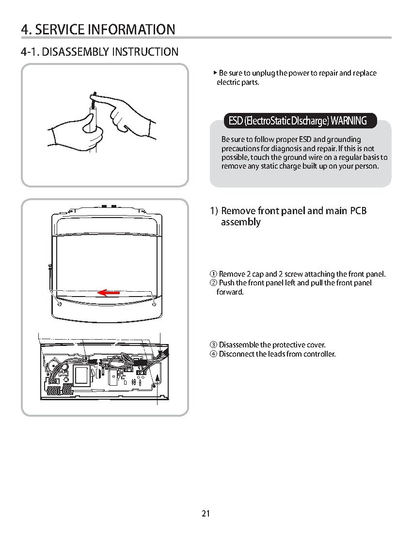
- Be sure to unplug the power to repair and replace electric parts.
ESD (ElectroStatic DIscharge) WARNING
Be sure to follow proper ESD and grounding precautions for diagnosis and repair. If this is not possible, touch the ground wire on a regular basis to remove any static charge built up on your person.
-
- Remove front panel and main PCB assembly
- ① Remove 2 cap and 2 screw attaching the front panel.
- ② Push the front panel left and pull the front panel forward.
- ③ Disassemble the protective cover.
- ④ Disconnect the leads from controller.
Noise Filter and Power Cord
- ① Remove the two screws attaching the noise filter.
- ② Disconnect both connectors in the noise filter. Remove the power cord from the noise filter.
Pressure Switch
- ① Disconnect the leads from pressure switch and detatch the pressure switch from the machine.
- ② Disconnect the pressure tube from the pressure switch.
2) Disassembly of the Noise Filter, Power Cord, Inlet Valve, Pressure Switch, and Dispenser Housing.
- ① Remove 2 screw attaching the panel on the back.
- ② Disassemble the rear panel.
Inlet Valve
- ① Disconnect the leads from the inlet valve and remove three screws.
- ② Remove the hoses and output pipes from the input valve.
- ③ Remove the inlet valve.
Dispenser Housing
- ① Remove the hoses and output pipes from the input valve.
- ② Disassemble the connector pipe and the dispenser housing.
3) Disassembly of Top Cover and Lid
- ① Remove 2screws attaching the back side of top cover.
- ② Remove 2screws that assembly the top cover with the front panel.
- ③ Lift the top cover at the front of the washer.
- ④ Remove the hinge cover and 6 hinge screw.
- ⑤ Pull the hinge to the left and right and Remove the hinge.
4) Disassembly of Tub Cover and Pulsator
- ① Remove 8 screws and take off the tub cover.
- ② Remove the pulsator cap.
- ③ Remove the pulsator screws.
- ④ Remove the pulsator washer.
5) Assemble the service tool (38 mm wrench)
6) Remove the hub attachment nut. (38 mm)
① Hit the bar using the hammer.
- ② Disconnect hub nut and disassemble the inner tub.
7) Disassembly of the Back Cover and Drain Pump
- ① Remove the screws that attach the back cover and take it off.
- ② Disconnect the leads and the drain hose from the drain pump.
- ③ Remove the pump attachment screws and the lead connector. Take the pump assembly out of the washer.
8) Disassembly of Damper Assembly
- ① Remove the top cover and the back cover of the washing machine.
- ② Pull out the hinge which connect the horizontal damper with outer tub.( To disassembly the horizontal damper, take the horizontal damper out of the holder.)
- ③ As shown in the drawing, lift the damper assembly and remove it along with the outer tub assembly.
- ④ Damper assembly shall not be disassembled. Replace damper as assembly.
9) Disassembly of Rotor and Stator
- ① Use a wrench (M24) to remove the nut that connects the rotor to the shaft. (The torque should be 200 kgf/cm or 88 footpounds.)
- ② Remove the rotor by pulling it straight off the splined shaft.
4-2. WIRING DIAGRAM
4-3. TEST RUNNING WITHOUT WATER
1) SAFETY CAUTION
- The main power board assembly has exposed live 120 VAC and live DC voltages. Use care when disconnecting connectors during troubleshooting and testing. (Wear electrostatic discharge gloves when handling the board.
- Unplug the power when handling the board assembly. (Wear electrostatic discharge gloves when handling the board. Store the board in an ESD [ElectroStatic Discharge] plastic bag.)
2) SERVICE MODE
The washer must be empty and the controls must be plugged in and turned off.
- Press and hold the SPIN and Water Plus button: then press the POWER button. The buzzer will sound twice.
- Press the Start/Pause button to advane to the subsequent test mode step.
| Numberoftimesthe START/PAUSE buttonispressed | CheckPoint | DisplayStatus |
|---|---|---|
| None | Main program version | t1 and main program version |
| 1 time | Display program version | t2 and display program version |
| 2 time | None | t3 |
| 3 time | Inlet valve for detergent turns on.(Cold Water) | Aand water level frequency(268 ~ 233) |
| 4 time | Inlet valve for detergent turns on.(Hot Water) | b and water level frequency(268 ~ 233) |
| 5 time | Inlet valve for softener turns on.(Cold Water) | C and water level frequency(268 ~ 233) |
| 6 time | Inlet valve for jet spray turns on.(Cold Water) | d and water level frequency(268 ~ 233) |
| 7 time | Inlet valve for bleach turns on.(Cold Water) | E and water level frequency(268 ~ 233) |
| 8 time | Heater check (on heater model) | |
| 9 time | Heater check (on heater model) | t5 and alphaRPM |
| 10 time | Drain pumpand agitate (pulsator) check | t6 and water level frequency(268 ~ 233) |
| 11 time | Load sensing Check | |
| 12 time | Agitate (tub) check | t8 andRPM |
| 13 time | Spin Check | t9 andRPM |
| 14 time | Off • Unlocks the door • Turns off all LED | None |
Table Caption: This table outlines the sequence of checks and display statuses triggered by successive presses of a START/PAUSE button, likely within a washing machine or similar appliance. Each button press corresponds to a specific diagnostic or operational check and a unique display status.
4-4. TROUBLESHOOTING BY COMMON WASHING PROBLEMS
Many washing problems involve poor soil and stain removal, residues of lint and scum, and fabric damage. For satisfactory washing results, follow these instructions.
Use ONLY powdered or liquid HE (High Effificiency) detergents. Do NOT use flakes scraped from a soap cake or bar, flakes, soap ribbons (available in some markets,) detergent tablets, plastic pouches, magic laundry balls, or anything
