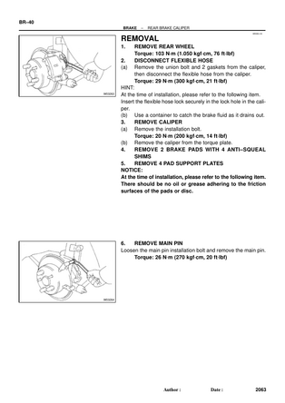
REMOVAL
- REMOVE REAR WHEEL
Torque: 103 N·m (1.050 kgf·cm, 76 ft·lbf)
- DISCONNECT FLEXIBLE HOSE
- (a) Remove the union bolt and 2 gaskets from the caliper, then disconnect the flexible hose from the caliper.
Torque: 29 N·m (300 kgf·cm, 21 ft·lbf)
HINT:
At the time of installation, please refer to the following it Insert the flexible hose lock securely in the lock hole in the per.
- (b) Use a container to catch the brake fluid as it drains o
- REMOVE CALIPER
- (a) Remove the installation bolt.
Torque: 20 N·m (200 kgf·cm, 14 ft·lbf)
- (b) Remove the caliper from the torque plate.
- REMOVE 2 BRAKE PADS WITH 4 ANTI-SQUEAL SHIMS
- REMOVE 4 PAD SUPPORT PLATES
NOTICE:
At the time of installation, please refer to the following item There should be no oil or grease adhering to the friction surfaces of the pads or disc.
- REMOVE MAIN PIN
Loosen the main pin installation bolt and remove the main pin.
Torque: 26 N·m (270 kgf·cm, 20 ft·lbf)
BR0B3-03
DISASSEMBLY
- REMOVE SLIDING BUSHING
- REMOVE 2 DUST BOOTS
- REMOVE MAIN PIN BOOT
NOTICE: Ensure that the boots are secured firmly to the bushing and caliper grooves.
- REMOVE CYLINDER BOOT SET RING AND BOOT (See step 1 on page BR-27 )
- REMOVE PISTON (See step 2 on page BR-27 )
- REMOVE PISTON SEAL (See step 3 on page BR-27 )
BR0B4-02
INSPECTION
- MEASURE PAD LINING THICKNESS
(See step 1 on page BR-28 )
Standard thickness:
10.0 mm (0.394 in.)
Minimum thickness: 1.0 mm (0.039 in.)
- MEASURE DISC THICKNESS
(See step 2 on page BR-28 )
Standard thickness: 10.0 mm (0.394 in.)
Minimum thickness: 9.0 mm (0.354 in.)
- MEASURE DISC RUNOUT
(See step 3 on page BR-28 )
Maximum disc runout: 0.15 mm (0.0059 in.)
If the disc's runout is maximum value or greater, check the bear ing play in the axial direction and check the axle hub runo (See page SA-52 ). If the bearing play and axle hub runout are not abnormal, adjust the disc runout or grind it on a 'On-Car brake lathe.
- IF NECESSARY, ADJUST DISC RUNOUT
- (a) Remove the 2 bolts and torque plate.
- (b) Remove the hub nuts and the disc. Reinstall the disc in the position turned 1/5 from its original position on hub. Install and torque the hub nuts.
Remeasure the disc runout. Make a note of the runout and the disc's position on the hub.
Torque: 103 N·m (1,050 kgf·cm, 76 ft·lbf)
- (c) Repeat (b) until the disc has been installed on the 3 r maining hub positions.
- (d) If the minimum runout recorded in (b) and (c) is less th 0.15 mm (0.0059 in.), install the disc in that position.
- (e) If the minimum runout recorded in (b) and (c) is greate than 0.15 mm (0.0059 in.), replace the disc and repeat step 3.
- (f) Install the torque plate and torque the mounting bolts.
Torque: 47 N·m (475 kgf·cm, 34 ft·lbf)
BR0B5-02
REASSEMBLY
Reassembly is in the reverse order of disassembly (See page BR-41 ). NOTICE:
Apply lithium soap base glycol grease to the parts indicated by the arrows (See page BR-24 ).
BR0B6-01
