Introduction
The Boxee Box is a cubist deviation from the traditionally rectangular set-top box. The oddly-shaped form factor forced D-Link to make the internals equally odd. But that also made it super fun to take apart!
We're also taking action against made-for-obsolescence devices with our Self-Repair Manifesto. Pay with a tweet and get a free poster!
What you need
-
-
Ladies and gentlemen, iFixit is proud to present the Boxee Box by D-Link.
-
It's hard to ignore how much taller the Boxee Box is than the Apple TV and Logitech Revue. This half-sunken cube will definitely stand out in your entertainment system.
-
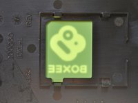
Yet, we feel that the Box has build quality that rivals Apple's, and is much more solid-looking than the Revue. The front panel is made of
glasssturdy plastic and displays a Boxee logo once you power on the device.
-
-
-
The Boxee Box looks huge when compared to the Apple TV, but it's really not that cumbersome in real life -- the Apple TV is just teeny tiny.
-
The Box' remote is only a tad bigger, but features a Qwerty keyboard that would come oh-so-handy on the Apple TV. Otherwise, spelling out "the lonely island" takes a while on YouTube.
-
It does remind us of a certain other Apple product, though...
-
-
-
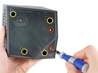
We had to peel off Boxee's lime-green rubber base and the adhesive sheet underneath to expose four #1 Phillips and two #2 Phillips screws.
-
The #2 Phillips screws are clearly visible when you peel off the rubber base.
-
The #1 Phillips are recessed, so you'll need a screwdriver with a longer shaft to access them.
-
-
-
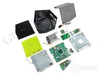
The bottom cover of the Boxee Box pulls off fairly easily, exposing all of its boxy goodness.
-
The Boxee Box gives us everything we want, and nothing we don't need:
-
HDMI out
-
Optical and analog (RCA) audio out
-
Ethernet
-
Two USB ports
-
The RCA jacks are a great addition for people who want to hook up the Boxee directly to computer speakers or retro stereo equipment.
-
-
-
-
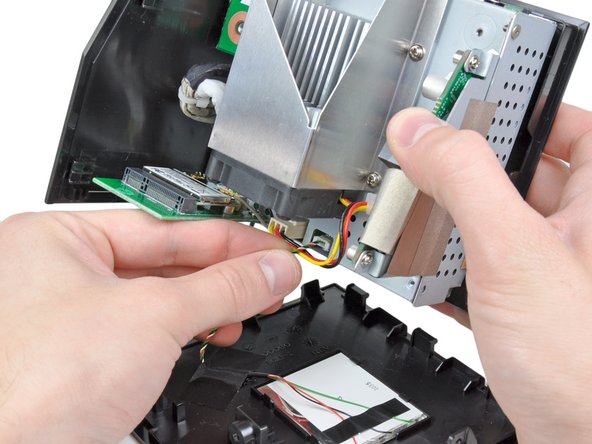
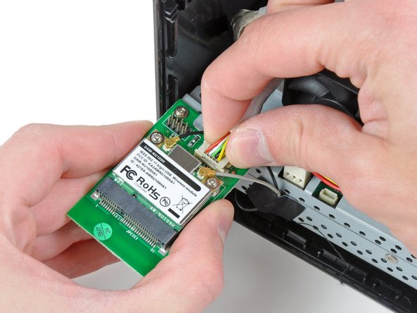
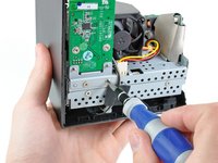
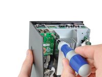
The Boxee Box' wireless board is secured to the metal frame by more Phillips screws.
-
It certainly is refreshing to see common screw types in electronics. When you don't need special tools to repair devices, it's easier to fix it yourself.
-
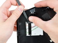
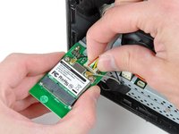
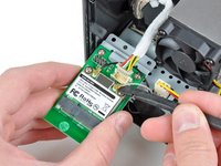
The wireless board is held on by a data connector and a couple antenna cables.
-
-
-
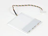
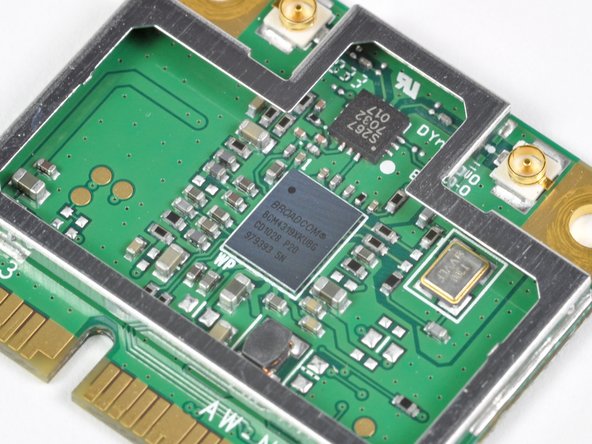
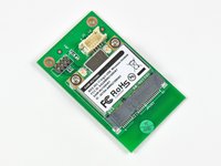
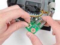
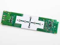
The wireless card assembly is composed of a Mini PCI-E wireless card and an interconnect board where the cable from the motherboard is connected.
-
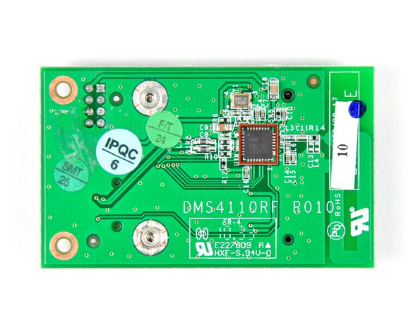
On the back side of the interconnect board we found a Nordic Semiconductor NRF24LU1P transceiver.
-
This chip is most likely used to decode signals received from the awesome QWERTY wireless remote.
-
We recently found the same chip in the Boxee's direct competitor, the Logitech Revue.
-
The Mini PCI-E wireless card employs a Broadcom BCM4319XKUBG.
-
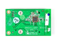
An remote control antenna is printed into the interconnect board right below the Mini PCI-E socket. This is positioned near the top of the device when it is assembled to aid in remote control reception.
-
-
-
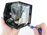
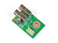
Next come the dual USB ports, which are mounted on a small PCB.
-
The PCB is connected by two #1 Phillips screws, as well as a connector that runs to the motherboard.
-
A thorough USB board analysis reveals a 220 μF capacitor, a PTC Fuse to protect against faulty USB devices, ESD Protection hardware (Clamp diodes and series inductors), and two USB sockets.
-
-
-
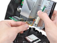
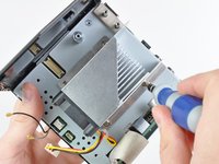
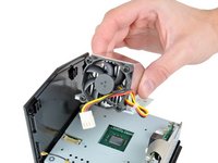
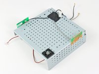
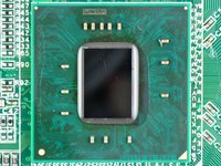
We progress by removing the fan and heatsink assembly from the CPU. It's time to find out what makes this baby tick.
-
Instead of using thermal paste, the Boxee Box uses a phase-change thermal pad much like the one found on the heat sink of the Logitech Revue.
-
-
-
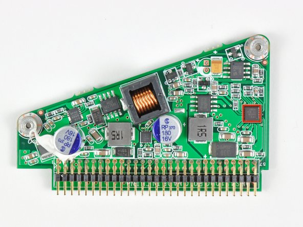
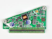
What do you find inside of an oddly-shaped device? An oddly-shaped power board, of course.
-
On this board we find:
-
-
-
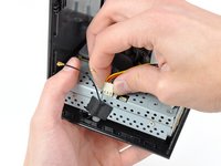
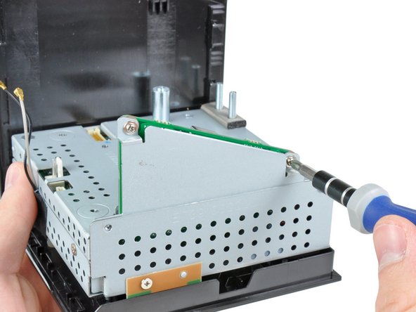
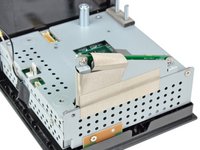
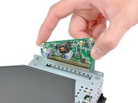
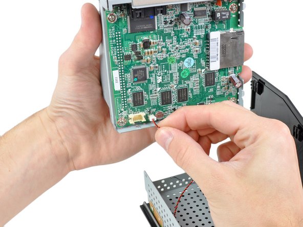
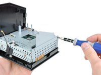
After removing a couple more Phillips screws, the motherboard can be removed from the rest of the metal frame.
-
Once it's lifted out, the power button connector is the only thing keeping us from getting a closer look at the board.
-
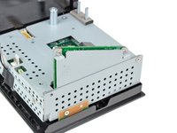
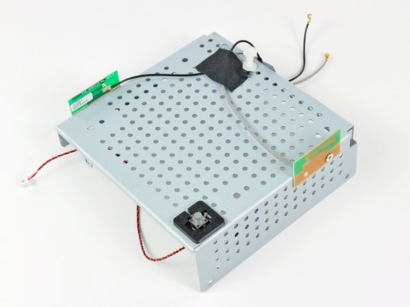
Once the motherboard is out, the bottom metal frame can be removed from the plastic outer casing.
-
The power button switch and dual antennas are mounted to the bottom metal frame, making it one compact unit.
-
-
-
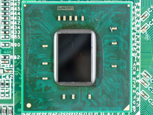
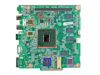
After popping off the top metal cover, we find:
-
Intel Atom CE4110 SOC processor
-
Wolfson WM8524G stereo DAC
-
AKM 8137A multi-clock generator
-
Nanya 1035 NT5CB128MCN-CG 512 MB DDR3 SDRAM (1/2 total RAM capacity)
-
RealTek RTL8201N 10/100 Ethernet PHYceiver
-
FE1.1 USB 2.0 HUB LG3A924A6180
-
-
-
The other side of the motherboard:
-
Toshiba NF3662 TC58NVG3S0ETA00 1 GB NAND Flash
-
LB TS21C HF 1031S
-
Microchip PIC24FJ64GA004-I/PT 16-bit microcontroller
-
Nanya NT5CB128M8CN-CG 512 MB DDR3 SDRAM (1/2 total RAM capacity)
-
-
-
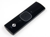
The Boxee Box's remote is very impressive. The front side has a basic directional pad with a select button in addition to separate play and menu buttons.
-
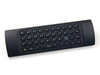
Instead of employing a full-sized keyboard like the Logitech Revue, Boxee Box engineers cleverly applied a mini QWERTY keyboard to the backside of the remote.
-
When we cracked the remote control open, we discovered a Nordic Semi NRF24LE1 for wireless connectivity to the Nordic Semi NRF24LU1P transceiver attached to the wireless interconnect board.
-
-
-
Boxee Box Repairability: 7 out of 10 (10 is easiest to repair)
-
The Boxee has a separate power board that can be replaced independently from the motherboard, should it ever fail.
-
All Phillips screws were used inside the device, requiring you to have just one screwdriver.
-
Once inside, all components come apart pretty logically.
-
The green rubber bottom of the Boxee Box is difficult to remove, and will never look the same once you've removed it.
-


6 Guide Comments
Was this a production board? What's with the rework at R12 (bottom left of the Atom, towards the ethernet port)? And the damaged-looking U707 IC (above center of Atom just below DIL socket)?
One of my capacitors in step 12 overheated and is leaking. This has broken my boxee, can anyone help me find the exact capacitor I should order?
Thank you,
Jamie
I take it that the memory in this unit is not upgradeable? Would be nice to refresh this box that is getting long in the tooth.
just came from Best Buy. Went there on a whim and fell on a streaming media universal remote by RCA. Paid $2.99 + tax. Bought it of course for my Boxee. Hope it works. Package says works with Dlink, Roku etc. Now all I need is a power adapter. Anyone know where i can buy a good for a similarly good price