Installing iPhone 4 Display Assembly Replacement

Featured Guide

Featured Guide

This guide has been found to be exceptionally cool by the iFixit staff.

Replace the display assembly in your iPhone 4.

  • Add Note x
  • x 243

Use this guide to replace your iPhone's display assembly. Replacing the display assembly will give you a new front glass panel, digitizer, and LCD. The LCD is adhered to the glass at the factory and the two parts are not separable without damage.

After successfully replacing the display assembly, protect your new display from scratches by installing a screen protector.

Image #1 Image #2

Add Note Edit Step 1 — Rear Panel  ¶ 

  • Your iPhone 4 rear cover may have either two #000 Phillips screws or Apple's 5-Point "Pentalobe" screws (second image). Check which screws you have, and ensure you also have the correct screwdriver in order to remove them.

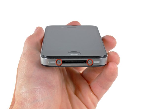
  • Remove the two 3.6 mm Pentalobe or Phillips #000 screws next to the dock connector.

  • During reassembly, we recommend you replace the 5-point screws with equivalent Phillips screws. Our Liberation Kit provides the tools and screws needed to replace the Pentalobe screws with Phillips screws.

Image #1 Image #2

Add Note Edit Step 2  ¶ 

  • Push the rear panel toward the top edge of the iPhone.

  • The panel will move about 2 mm.

Image #1

Add Note Edit Step 3  ¶ 

  • Pinch the rear panel with your fingers and lift it away from the iPhone.

Image #1 Image #2

Add Note Edit Step 4 — Battery  ¶ 

  • Remove the single 2.5 mm Phillips screw securing the battery connector to the logic board.

    • Some devices may have two screws, one of which holds down the contact pad which is located above the screw indicated in red in the photo.

  • Use a plastic opening tool to gently disconnect the battery connector from its socket.

Image #1 Image #2 Image #3

Add Note Edit Step 5  ¶ 

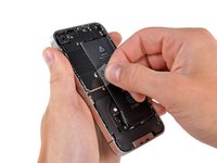
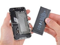
  • Use the clear plastic pull tab to gently lift the battery out of the iPhone.

  • Be careful when removing the battery with the plastic pull tab. On some units, Apple uses an excessive amount of glue, making it virtually impossible to remove the battery in this fashion (with the tab possibly tearing due to excessive force).

  • For batteries that "stick", you could use the iPod opening tool to assist (take extra care whilst doing so).

  • You might find it easier to pry the battery out from the right-hand side because no glue is used on this side.

  • Remove the battery.

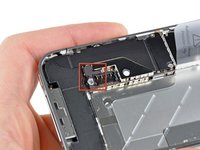
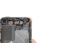
  • Before reconnecting the battery connector, be sure the pressure contact (shown in red) is properly positioned next to the battery connector.

  • Before reassembly, be sure to clean all metal-to-metal contact points on the pressure contact as well as its contact point on the rear panel with a de-greaser such as Windex (96% ethanol alcohol works well too, but make sure that contacts are dry when done). The oils on your fingers have the potential to cause wireless interference issues.

Image #1 Image #2

Add Note Edit Step 6 — Logic Board  ¶ 

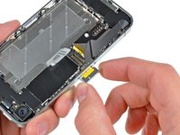
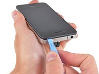
  • Use a SIM card eject tool or a paperclip to eject the SIM card and its holder.

  • This may require a significant amount of force.

  • Remove the SIM card and its holder.

Image #1 Image #2

Add Note Edit Step 7  ¶ 

  • Remove the following two screws:

    • One 1.2 mm Phillips

    • One 1.6 mm Phillips

  • Remove the thin steel dock connector cable cover from the iPhone.

  • Before reassembly, be sure to clean all metal-to-metal contact points on the dock connector cable cover with a de-greaser such as windex. The oils on your fingers have the potential to cause wireless interference issues.

Image #1 Image #2

Add Note Edit Step 8  ¶ 

  • Use an iPod opening tool to gently pry the dock cable connector up off the logic board from both short ends of the connector.

Image #1 Image #2

Add Note Edit Step 9  ¶ 

  • Carefully peel the dock ribbon cable off the logic board and the lower speaker enclosure.

  • Do not use excessive force to peel the dock ribbon cable off the logic board. Doing so may tear the cable.

Image #1

Add Note Edit Step 10  ¶ 

  • Use an iPod opening tool to pry the lower antenna connector up off its socket on the logic board.

Image #1

Add Note Edit Step 11  ¶ 

  • Remove the 1.9 mm Phillips screw securing the bottom of the logic board to the inner case.

Image #1

Add Note Edit Step 12  ¶ 

  • Remove the following five screws securing the Wi-Fi antenna to to the logic board:

    • One 2.3 mm Phillips

    • Two 1.6 mm Phillips

    • One 1.4 mm Phillips

    • One 4.8 mm Phillips

  • When re-assembling, start off with replacing the 4.8 mm Philips screw first, then the 2.3 mm. This is to ensure there is no mix-up, and avoid rendering the LCD and digitizer useless.

  • Also make sure to put the long 4.8 mm Philips back in correctly when reassembling. This is the ground for the Wi-Fi antenna and is often the culprit if you are having bad Wi-Fi reception after reassembly.

Image #1 Image #2 Image #3

Add Note Edit Step 13  ¶ 

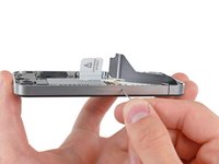
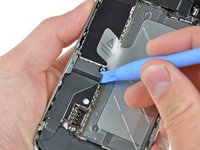
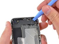
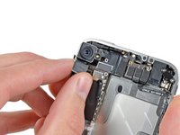
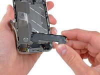
  • Use an iPod opening tool to slightly lift the top edge of the Wi-Fi antenna away from the logic board.

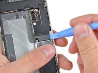
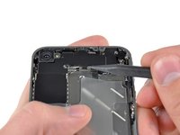
  • Use the tip of a spudger to pull the Wi-Fi retaining clips away from the inner frame.

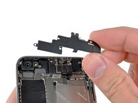
  • Remove the Wi-Fi antenna from the iPhone. Make sure you don't lose the metal clips on the top of the cover where the 4.8mm screw attaches or the 4.8mm screw. That's the primary reason for abnormal Wi-Fi performance after the reassembly.

  • Before reassembly, be sure to clean all metal-to-metal contact points on the connector cover with a de-greaser such as Windex. The oils on your fingers have the potential to cause wireless interference issues. Do not clean the connectors themselves with Windex.

Image #1 Image #2

Add Note Edit Step 14  ¶ 

  • Use an iPod opening tool to carefully lift the rear camera connector up off its socket on the logic board.

  • Remove the rear camera.

Image #1 Image #2

Add Note Edit Step 15  ¶ 

  • Remove the small circular white sticker (warranty sticker and water indicator) covering the screw near the battery pull tab.

  • Remove the 2.4 mm Phillips screw that was hidden underneath the sticker.

Image #1

Add Note Edit Step 16  ¶ 

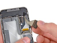
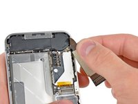
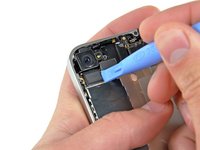
  • Use the edge of a plastic opening tool to gently pry the following connectors up and out of their sockets on the logic board:

    • Digitizer cable (pry from bottom)

    • LCD cable (pry from bottom)

    • Headphone jack/volume button cable (pry from top)

    • Top Microphone/sleep button cable (pry from top)

    • Front camera cable (pry from top)

Image #1

Add Note Edit Step 17  ¶ 

  • Use a small flathead screwdriver to remove the 4.8 mm standoff near the headphone jack.

  • When reassembling the device, this standoff sets the height of the Wi-Fi shield removed in step 13. If not torqued down, the shield will be above the plane of the frame and the back will not slide into place in step 2. The shield should be flush with the headphone jack.

  • When reassembling the motherboard, ensure that its edge sits under the circled standoff, otherwise the screws will not fit.

  • When reassembling ensure that the small rubber spacer attached to the top of the motherboard is in place. Without this part the motherboard could damage the ribbon cables around it.

Image #1

Add Note Edit Step 18  ¶ 

  • Carefully remove the logic board from the iPhone, minding any cables that may get caught.

    • Be careful not to damage the small gold prong (marked in red, near the top) as it's very fragile.

Image #1

Add Note Edit Step 19 — Speaker Enclosure Assembly  ¶ 

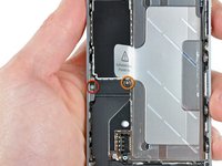
  • Remove the single 2.4 mm Phillips screw securing the speaker enclosure to the side of the inner frame.

Image #1 Image #2

Add Note Edit Step 20  ¶ 

  • Remove the speaker enclosure from the iPhone.

  • Before re-fastening the speaker enclosure to the inner frame, be sure the four small EMI fingers rest below the lip of the LCD frame.

  • Before reassembly, be sure to clean all metal-to-metal contact points between the EMI fingers and the internal frame as well as the brass screw mounting point with a de-greaser such as Windex. The oils on your fingers have the potential to cause wireless interference issues.

Image #1 Image #2

Add Note Edit Step 21 — Display Assembly  ¶ 

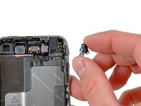
  • Remove the following two screws securing the vibrator to the inner frame:

    • One 6 mm Phillips

    • One 1.4 mm Phillips

  • Remove the vibrator from the iPhone.

Image #1

Add Note Edit Step 22  ¶ 

  • Remove the 1.5 mm Phillips screw securing the front panel near the headphone jack.

Image #1

Add Note Edit Step 23  ¶ 

  • Remove the three large-headed 1.5 mm Phillips screws along the volume button side of the iPhone.

  • Keep track of the washers under each of the screws.

  • Tip: It can be tricky, but it is also possible to just loosen the large-headed 1.5 mm Phillips screws slightly, without having to remove and replace the screw-and-washer set.

Image #1

Add Note Edit Step 24  ¶ 

  • Remove the 1.5 mm Phillips screw near the lower microphone.

Image #1

Add Note Edit Step 25  ¶ 

  • Remove the 1.5 mm Phillips screw near the dock connector ribbon cable.

Image #1

Add Note Edit Step 26  ¶ 

  • Remove the three large-headed 1.5 mm Phillips screws along the SIM card side of the iPhone.

  • Keep track of the washers under each of the screws.

  • Tip: It can be tricky, but it is also possible to just loosen the large-headed 1.5 mm Phillips screws slightly, without having to remove and replace the screw-and-washer set.

  • Remove the small-headed 1.5 mm Phillips screw near the sleep button.

Image #1 Image #2

Add Note Edit Step 27  ¶ 

  • Carefully insert the edge of an iPod opening tool between the rubber bezel around the front glass panel and the steel inner frame.

  • Do not attempt to insert the tool between the glass and the rubber bezel.

  • Carefully pry the upper edge of the front panel assembly away from the steel inner frame.

Image #1 Image #2

Add Note Edit Step 28  ¶ 

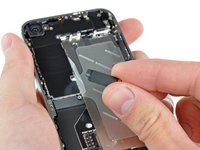
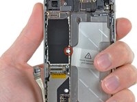
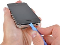
  • Slowly and gently lift the top edge of the front panel assembly away from the steel inner frame.

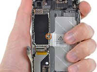
  • Continue to rotate the front panel assembly away from the steel inner frame until it slowly begins to peel off the adhesive applied below the home button area.

    • It may be easiest to insert a spudger at the top and work it around the edges, spreading gently as you go.

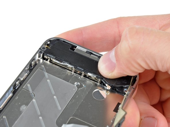
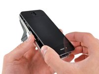
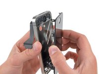
  • Carefully pull the lower edge of the front panel assembly away from the steel inner frame.

  • Be careful, if the home button sticks to the front panel you may tear the home button cable.

  • Do not flip the front glass completely away from the frame. Doing so may result In damage to the digitizer cable.

Image #1

Add Note Edit Step 29  ¶ 

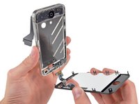
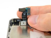
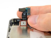
  • De-route the digitizer and LCD cables through the steel inner frame.

  • Before re-fastening the front panel to the steel inner frame, be sure both the LCD and digitizer cables are not folded or pinched between the inner frame and the front panel assembly. This will result in possibly damaging the cables and not having enough slack when reconnecting them to the logic board.

  • When the front panel has been correctly installed both the LCD and digitizer cables should be immediately next to one another and should be the same length and should be just hanging over the steel frame.

  • When replacing the front panel assembly you must remember that you might have to reuse the earpiece grille and the clear plastic ring around the front facing camera from the old/damaged assembly. This will depend on where you buy the replacement part.

  • After reassembly, protect your new display from any scratches by installing a new screen protector.

Image #1

Add Note Edit Step 30 — Display Assembly Replacement  ¶ 

  • Your replacement display may come with a red plastic film on the back of the LCD.

  • If it does, use the pull tab near the home button to peel the plastic film from the LCD before installing the new display in your iPhone.

Required Tools

Spudger

$2.95 · 50+ In stock

Phillips #00 Screwdriver

$4.95 · 50+ In stock

Flathead 3/32" or 2.5 mm Screwdriver

$4.95 · 50+ In stock

Plastic Opening Tools

$2.95 · 50+ In stock

iPhone 5-Point Pentalobe Screwdriver

$12.95 · 50+ In stock

Related Products

Recommended Tools

Universal Drive Adapter

$29.95 · 50+ In stock

Inspection Scope

$39.95 · 17 In stock

Portable Anti-Static Mat

$24.95 · 10 In stock

Comments Add Note Comments are offturn on