
This teardown is not a repair guide. To repair your iriver Multi-Codec Jukebox H10, use our service manual.

  1. iriver Multi-Codec Jukebox H10 Partial Teardown, iriver Multi-Codec Jukebox H10 Partial Teardown: step 1, image 1 of 1
    • Brand: iriver

    • Model: Multi-Codec Jukebox H10

    • Retail Price: ~$70 (?)

    • Release Date: Unknown

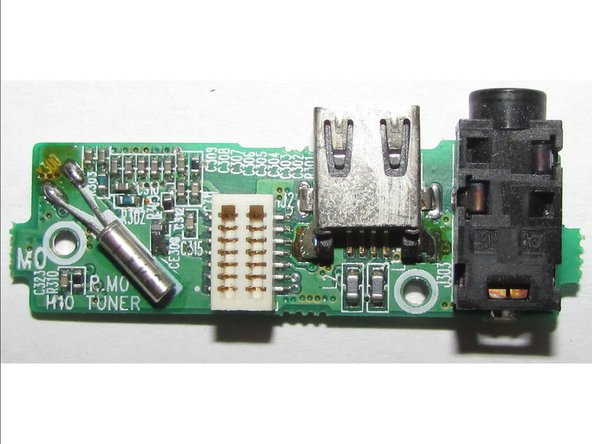
    • Connectivity: USB 2.0; 18 pin connector; stereo mini-jack; connector for wired remote control

    • Note: This picture is from Guru3D; all other pictures in this report are taken by me.

  2. iriver Multi-Codec Jukebox H10 Partial Teardown: step 2, image 1 of 2 iriver Multi-Codec Jukebox H10 Partial Teardown: step 2, image 2 of 2
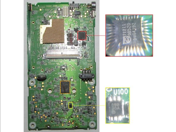
    • Main PCB Front Side Chip Identification (Part 1):

    • PortalPlayer PP5020E-TF Media Processor

    • Samsung Semiconductor K4S561633F 4M x 16Bit x 4 Banks Mobile SDRAM

    • NXP Semiconductors (?) 74LV4052 Dual 4-channel analog Multiplexer/Demultiplexer

    • Wolfson Microelectronics WM8731 Portable Internet Audio CODEC with Headphone Driver and Programmable Sample Rates

    • Linear Technology LTC4055 USB Power Controller and Li-Ion Charger

  3. iriver Multi-Codec Jukebox H10 Partial Teardown: step 3, image 1 of 1
    • Main PCB Front Side Chip Identification (Part 2):

    • Epson RTC-8564JE Real Time Clock Module

    • Unknown LAGKJ575451 (?) Unknown

    • Unknown R2R (?) Voltage Regulator (?)

  4. iriver Multi-Codec Jukebox H10 Partial Teardown: step 4, image 1 of 2 iriver Multi-Codec Jukebox H10 Partial Teardown: step 4, image 2 of 2
    • Main PCB Back With Storage Unit Identifications:

    • Storage Unit 5 GB

    • Side Button PCB

    • 3.3v 0.22F Super Capacitor

    • Battery Pack Contacts

  5. iriver Multi-Codec Jukebox H10 Partial Teardown: step 5, image 1 of 2 iriver Multi-Codec Jukebox H10 Partial Teardown: step 5, image 2 of 2
    • Main PCB Back Chip Identification:

    • NXP Semiconductors TEA1211 High efficiency auto-up/down DC/DC converter

    • Microchip Technology SST89VF800A 8 Mbit (x16) Multi-Purpose Flash

    • Unknown O9B20A (?) Unknown

  6. iriver Multi-Codec Jukebox H10 Partial Teardown: step 6, image 1 of 2 iriver Multi-Codec Jukebox H10 Partial Teardown: step 6, image 2 of 2
    • Storage Unit Annotations:

    • Breather Hole

    • Rubber Shock Absorbing Bumpers

    • Flat Flex Cable

    • Storage Unit Type: Seagate ST650211FX 5GB Hard Drive with Flex Cable

  7. iriver Multi-Codec Jukebox H10 Partial Teardown: step 7, image 1 of 2 iriver Multi-Codec Jukebox H10 Partial Teardown: step 7, image 2 of 2
    • Back Casing Annotations:

    • FM Radio Section

  8. iriver Multi-Codec Jukebox H10 Partial Teardown: step 8, image 1 of 3 iriver Multi-Codec Jukebox H10 Partial Teardown: step 8, image 2 of 3 iriver Multi-Codec Jukebox H10 Partial Teardown: step 8, image 3 of 3
    • Back Casing Connector Board Chip Identifications:

    • NXP Semiconductors TEA5767HN Low-power FM stereo radio for handheld applications

  9. iriver Multi-Codec Jukebox H10 Partial Teardown: step 9, image 1 of 2 iriver Multi-Codec Jukebox H10 Partial Teardown: step 9, image 2 of 2
    • Battery Pack:

  10. iriver Multi-Codec Jukebox H10 Partial Teardown: step 10, image 1 of 2 iriver Multi-Codec Jukebox H10 Partial Teardown: step 10, image 2 of 2
    • Battery Pack without Cover Annotations:

    • Screw Hole Metal Pieces

    • Protection Circuit

    • Battery Cell

  11. iriver Multi-Codec Jukebox H10 Partial Teardown: step 11, image 1 of 1
    • Li-ion Battery Identification:

    • Unknown IKIPK3 019778 11815322 (?) 3.7V Lithium Ion Battery

  12. iriver Multi-Codec Jukebox H10 Partial Teardown: step 12, image 1 of 2 iriver Multi-Codec Jukebox H10 Partial Teardown: step 12, image 2 of 2
    • Battery Protection Circuit Annotations:

    • Battery Negative Contact

    • Battery Positive Contact

    • Battery Pack Contacts

  13. iriver Multi-Codec Jukebox H10 Partial Teardown: step 13, image 1 of 1
    • Battery Protection Circuit Chip Identification:

    • Mitsumi MM3210 (?) Battery Protection

  14. iriver Multi-Codec Jukebox H10 Partial Teardown: step 14, image 1 of 1
    • Design wins for this device:

  15. iriver Multi-Codec Jukebox H10 Partial Teardown: step 15, image 1 of 1
    • Predicted block diagram for this device:

CChin

Member since: 06/10/20

6,216 Reputation

7 Guides authored

One Comment

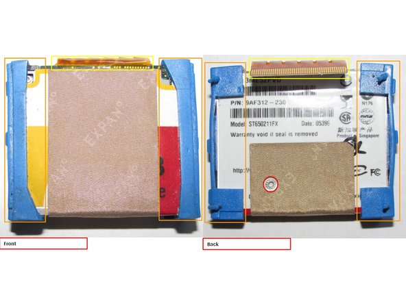
Hi, I have a question about the HDD ribbon cable. How do i take it out from the board? Are there any latches that I need to pop up after which the white part should slide out?

Maneesh Sharma - Reply

Add Comment

View Statistics:

Past 24 Hours: 1

Past 7 Days: 5

Past 30 Days: 23

All Time: 1,672