Introduction
This guide will run through how to teardown a wireless charging pad. It is quite simple and doesn't take much time at all. Enjoy!
What you need
-
-
First thing to do is remove the pad that covers the screws. This is what the phone sits on when charging (on top of device).
-
Use a spudger or some other kind of flat tool you can pry under the padding with to loosen the adhesive and pry off.
-
Pry gently as you don't want to rip or tear this padding. NOTE: It is only held on with a sticky adhesive tape.
-
-
-
Once you have removed the padding ring you will notice (4) phillip head screws.
-
Use a small screwdriver to remove these screws. (I used a #1.2 phillip head screwdriver).
-
Once the screws are removed you should be able to remove the bottom cover of the device exposing the circuit board.
-
-
-
Once you have the bottom cover off you can access the circuit board and charging unit.
-
To access the top of the charging unit just pry away the top cover and the piece the circuit board is connected to.
-
-
-
-
To remove circuit board: There are two clips holding the board in place (see photo 1). Using a spudger or a flat tool pry one of the clips away while lifting up on that end of the board. Once the board clears the clip the board will come out.
-
To remove charging unit: The charging unit is held in by adhesive and connected to the circuit board (see photo 3). Just pry from adhesive.
-
-
-
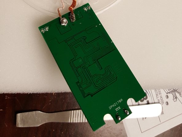
Whether replacing circuit board or charging unit... Any work done here will have to be soldered.
-
The charging unit is soldered to the back of the circuit board. (see photo)
-
-
-
You can put back together in reverse order.
I have two of these Samsung chargers and neither one of them have screws under the rubber ring.
-


6 Comments
If you don't like the beep, disable the speaker. If the speaker is surface mounted it can't be easily disconnected. Use a drop or two of superglue inside to silence it.
this is for the fake one, what about the original one? it doesnt have this screws
Ditto that fake
It’s fake ditto
The fast charger has a bottom rubber pad surrounding the ID plate. Under the pad are two small Philips Head screws - remove the pad carefully, it can be reused. Screws need to be removed to “unlock” the top / bottom and allow the top to be turned counter clockwise to unlock the four locking lugs. Once separated there are a number of screws holding the inner parts in place. Keep them grouped and note where they came from. There is a circuit board on one side, the coil on the other. The fan is sandwiched between the two haves, and connects to the board via red/black wires and a quick connector. There is not much slack, and the connector is anything but quick.
Re-assembly is in reverse order.
Good luck.
The comment about “for original samsung chargers” should be closer to the top as this step instructions are wrong.
Tom Karches - Reply