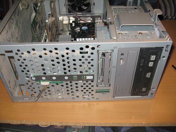
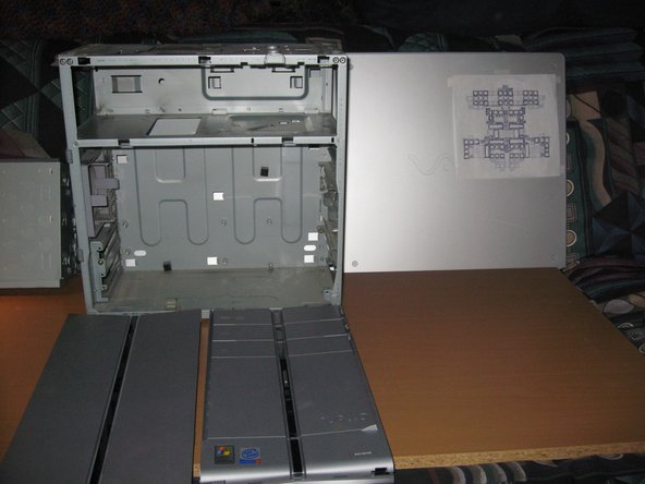
At the time it was released it was a very half decent computer. Sony Deemed this model a Digital Studio because of all its Audio and Video inputs and outputs. It has Video inputs on the front panel and optical audio and DVI Video outs on the rear. There is also a Mpeg Decoder/Encoder board for use with recording television via Cable Conection and an infrared remote to control certain programs with (Giga Pocket). I have Upgraded a few things including adding another Hard Drive and maxxed the Memory to a stunning 1.5gb.
If you use this information to upgrade this PC, take in mind that it may be easier to skip some steps say if your going to install new memory or another hard drive as I've done.
So here it is, The Systematic Disassembly
To Really be Blown Away By the Magic - Watch in Slideshow,
-Link Below-
What you need
This teardown is not a repair guide. To repair your Sony Vaio PCV-RZ14G, use our service manual.
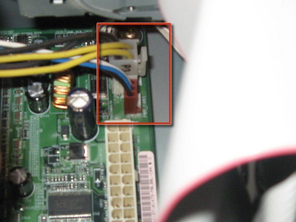
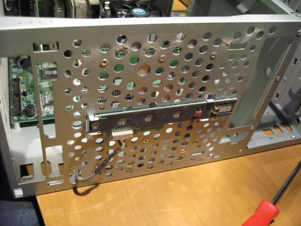
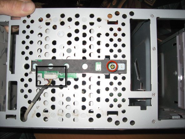
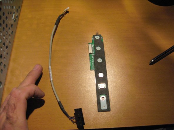
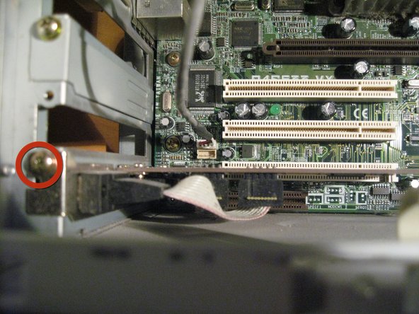
Remove the Sony Memory card reader by unplugging it from the motherboard and unscrewing the single screw (in red). Then simply slide it out of it's little niche
Our first little piece of proprietary MAGIC. Alot of Sony Devices at the time this was sold and still today have only SONY MEMORY STICK / Magic Gate Readers. I'm not sure if SD cards were really prominent as they are today. Regardless, they wanted it to work primarily with their equipment.
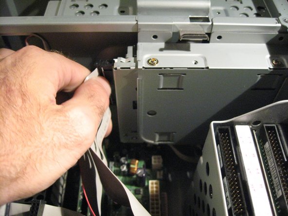
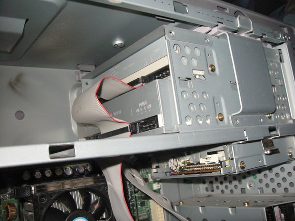
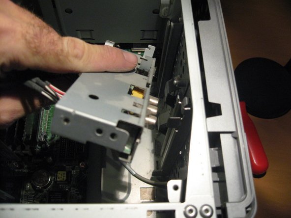
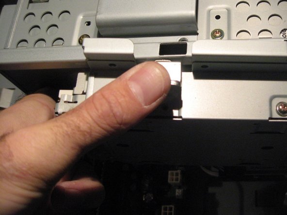
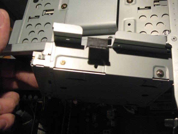
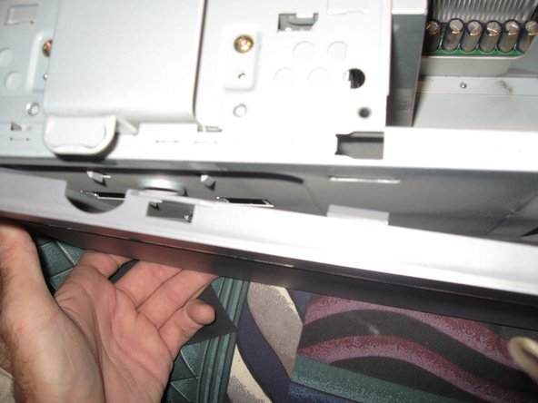
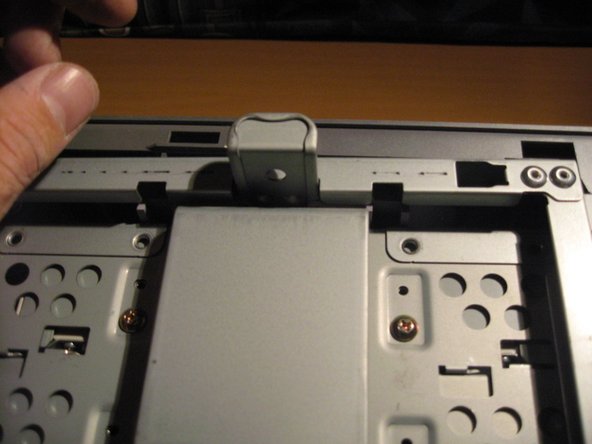
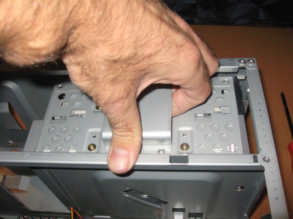
Next we will remove both of the Optical Disk Drives.
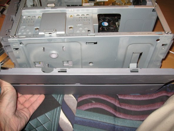
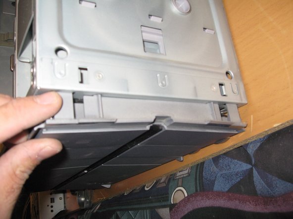
Pull up on latch, releasing the lock enabling you to pull up on drive box assembly and lift out of case
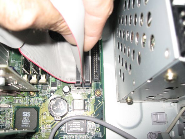
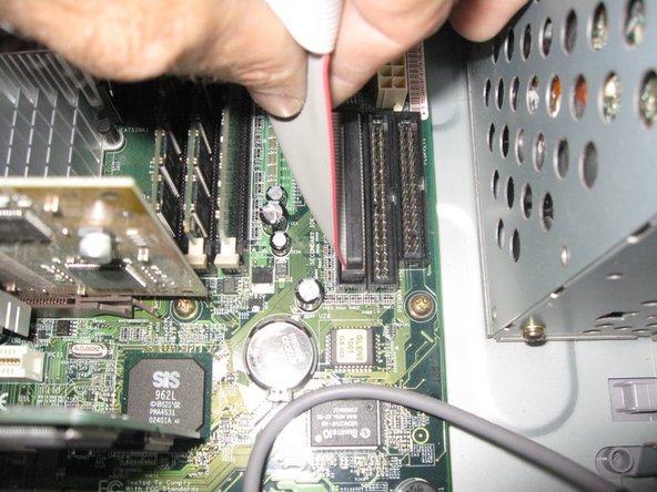
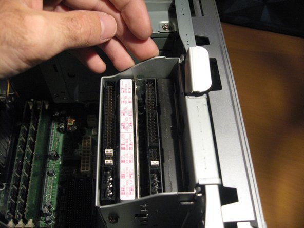
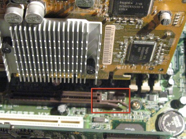
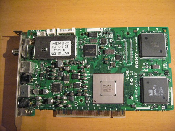
Next is the PCI Mpeg Decoder Board. Remove the Cable that connects from the motherboard to the card.
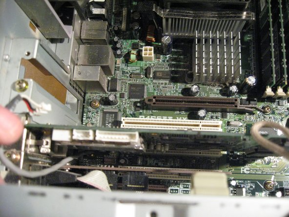
Unscrew and remove the Mpeg/Video In Board.
This MPEG ENCODER/DECODER board is another piece of Sony proprietary MAGIC. I say this because the only software that works with this Hardware is made by SONY. GIGA POCKET by the way, at this point in time was a pretty crappy combo.
And remove the Last PCI Card by unscrewing the single Screw. This card is a PCI -Serial Port adapter.
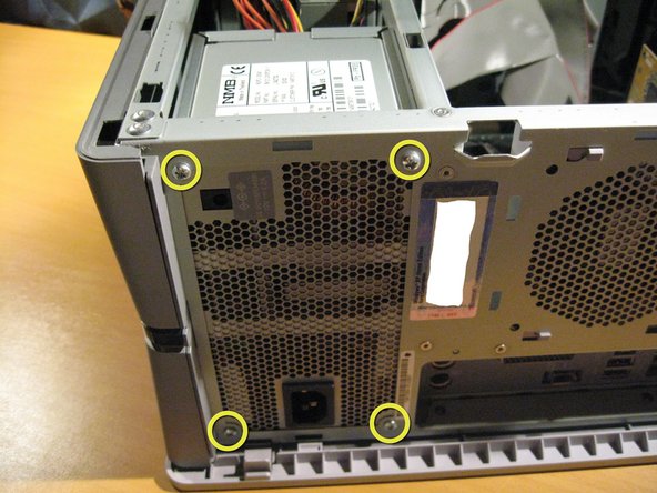
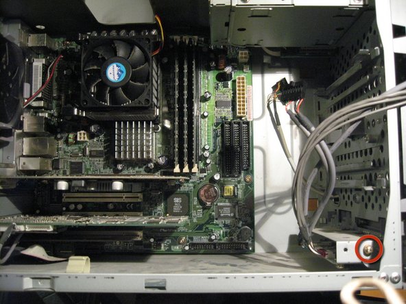
Now to remove the Motherboard-Remove Labeled Screws in image
Be Careful to keap mind of the connection ports on the rear of the Motherboard while removing. So your going to want to lift it out first on the right side then the side with the ports.
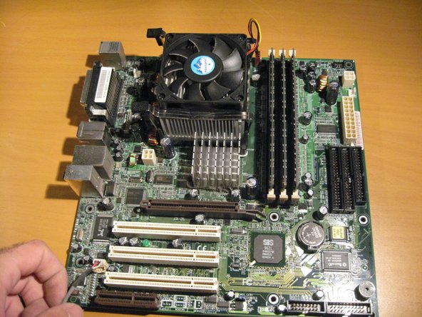
Now lift the Motherboard out of the Case
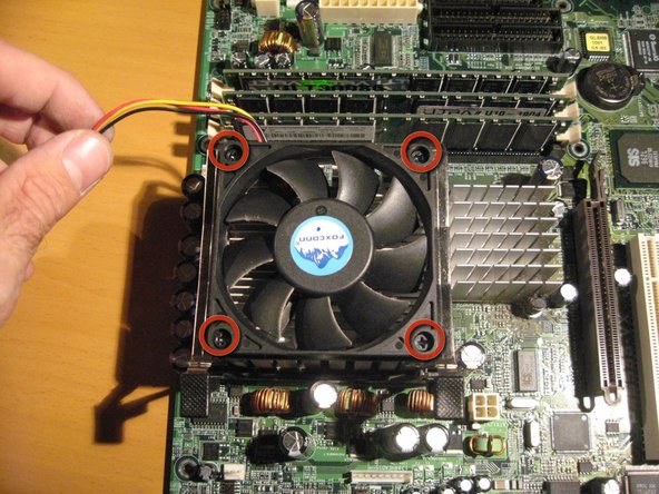
Disconnect the PC fan from the motherboard, Unscrew the four screws and remove.
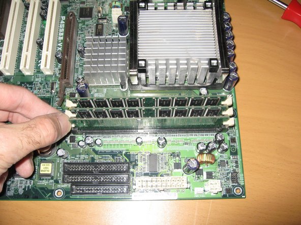
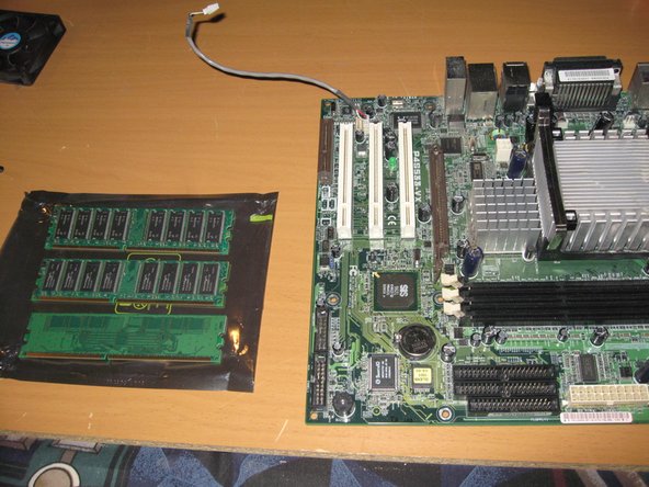
Keep memory in a safe place because it is prob one of the most volatile components of your PC and is known to get messed up easliy from Static Electricity.
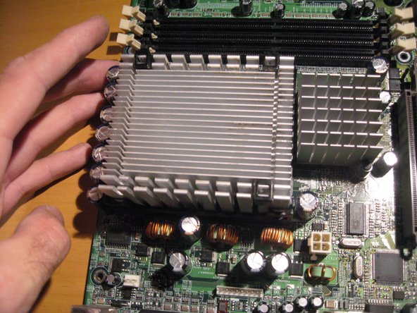
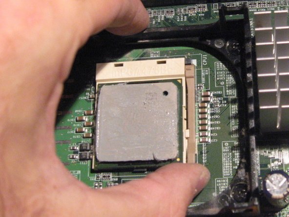
In order to remove heatsink, apply pressure to the far side and pull out of latch on near side (Use Both hands).
After Releasing clips lift up and remove heatsink.
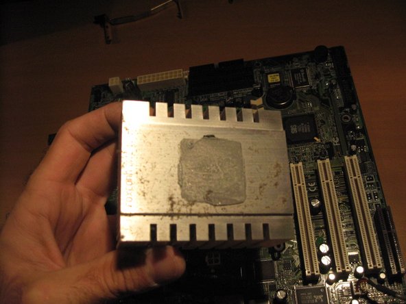
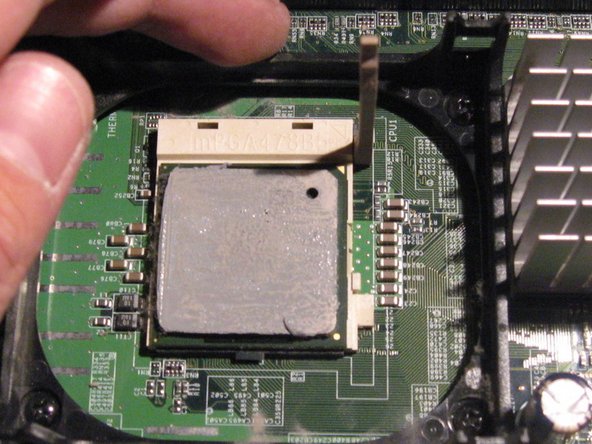
The underside of the heatsink will have thermal paste so when removed place on its top in order not to make a mess. And in this case it has a bit of dust accumulated.
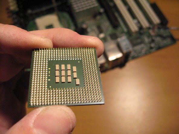
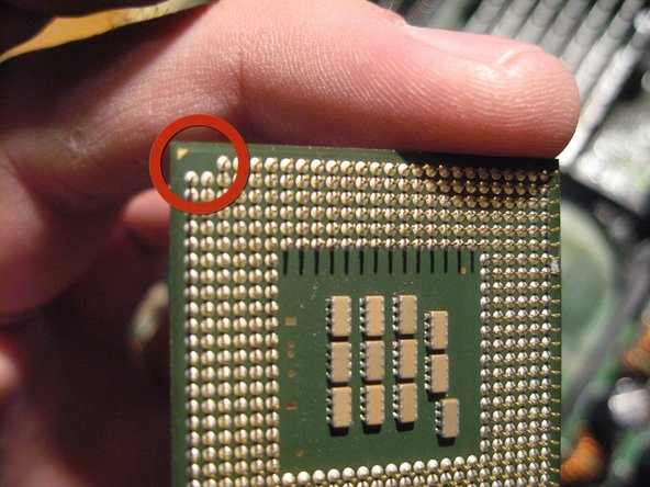
Take note of the one corner that has a few pins missing and a guide arrow. This processor chip will fit into the PGA one way and this serves as a guide.
Note , another guide arrow on the topside of the chip.
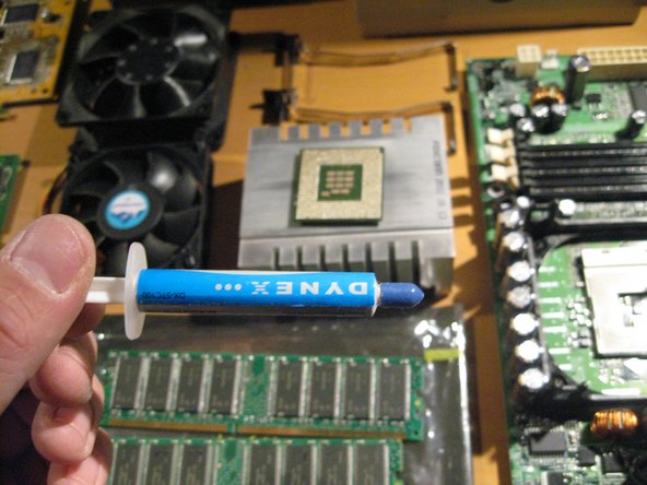
I am going to clean the thermal paste off of the Processor and the heatsink and add a new application. This is not particularly needed but in this case i felt i would.