
What you need

This teardown is not a repair guide. To repair your Qoobo - Robot Pillow with a Tail, use our service manual.

  1. Qoobo Teardown, Remove outer cover: step 1, image 1 of 3 Qoobo Teardown, Remove outer cover: step 1, image 2 of 3 Qoobo Teardown, Remove outer cover: step 1, image 3 of 3
    • Unzip, and remove.

  2. Qoobo Teardown, Remove screws near charging port: step 2, image 1 of 2 Qoobo Teardown, Remove screws near charging port: step 2, image 2 of 2
    • Remove the circular sticker around the charging port. This reveals two screws, which should also be removed.

  3. Qoobo Teardown, Remove screws under power button: step 3, image 1 of 2 Qoobo Teardown, Remove screws under power button: step 3, image 2 of 2
    • The power button can be dislodged with a small knife, revealing another 2 screws.

    • Once these screws are removed, the plastic plate should come loose and can be removed.

  4. Qoobo Teardown, Remove the inner cushion shell: step 4, image 1 of 3 Qoobo Teardown, Remove the inner cushion shell: step 4, image 2 of 3 Qoobo Teardown, Remove the inner cushion shell: step 4, image 3 of 3
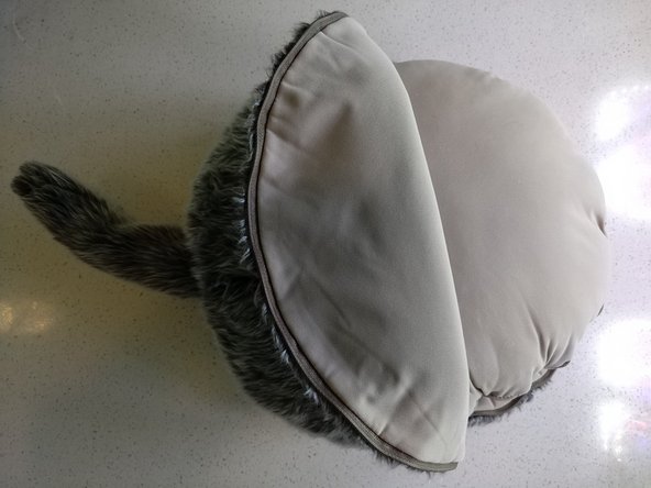
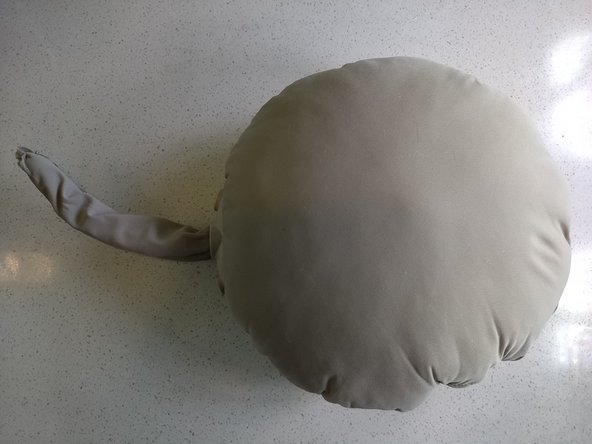
    • Unzip the inner fabric shell, and remove the plastic "heart" of the device.

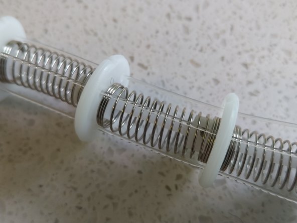
    • The tail has 2 degrees of freedom. One servo is used for the X axis, another for the Y axis. The tail itself is made up of springs, with stretchable cables acting as "tendons"

  5. Qoobo Teardown, Close ups of the main board: step 6, image 1 of 3 Qoobo Teardown, Close ups of the main board: step 6, image 2 of 3 Qoobo Teardown, Close ups of the main board: step 6, image 3 of 3
    • U1: reads "CB5121". Probably a PMIC

    • U4: Unmarked 32 pin IC is almost certainly the main microcontroller.

    • U3: BMA223 Accelerometer (used for detecting motion, for when the pillow should wag its tail)

    • U7: Unmarked 14 pin IC.

    • There is an unpopulated 6 pin header that looks like a serial port (UART)

    • There is an unpopulated 8 pin header that is probably for debug / flashing

  6. Qoobo Teardown, Other boards: step 7, image 1 of 3 Qoobo Teardown, Other boards: step 7, image 2 of 3 Qoobo Teardown, Other boards: step 7, image 3 of 3
    • Simple board for the power switch.

    • Another board has the charging port and LED

    • Ni-MH battery rated at 6.0V and 1300mAh

  7. Qoobo Teardown: step 8, image 1 of 3 Qoobo Teardown: step 8, image 2 of 3 Qoobo Teardown: step 8, image 3 of 3
    • Servos are unmarked, but appear to be standard hobby-grade servos.

Nic Dahlquist

Member since: 09/26/20

157 Reputation

1 Guide authored

View Statistics:

Past 24 Hours: 1

Past 7 Days: 3

Past 30 Days: 7

All Time: 921