Introduction
Oculus finally catches up with the big boys with the release of their ultra-responsive Oculus Touch controllers. Requiring a second IR camera and featuring a whole mess of tactile and capacitive input options, these controllers are bound to be chock full of IR LEDs and tons of exciting tech—but we'll only know for sure if we tear them down!
Want to keep in touch? Follow us on Instagram, Twitter, and Facebook for all the latest gadget news.
What you need
-
-
Before we tear down, we take the opportunity to ogle the Oculus Touch system, which includes:
-
An additional Oculus Sensor
-
A Rockband adapter
-
Two IR-emitting Touch controllers with finger tracking and a mess of buttons
-
-
-
Using our
spectrespecsfancy IR-viewing technology, we get an Oculus Sensor eye's view of the Touch controllers. -
While the twin black plastic halos are featureless to the naked eye, our camera sees the double rings of infrared LEDs residing beneath.
-
The LEDs, like those present in the headset, are arranged in distinct patterns, allowing the Oculus Sensor to pick out the headset and two controllers and determine their position and orientation.
-
Also, thanks to the not-quite-round shape of each controller, the sensor ought to be able to tell left from right—even after you've crossed your arms while playing Disappointed Parent Simulator 2016.
-
-
-
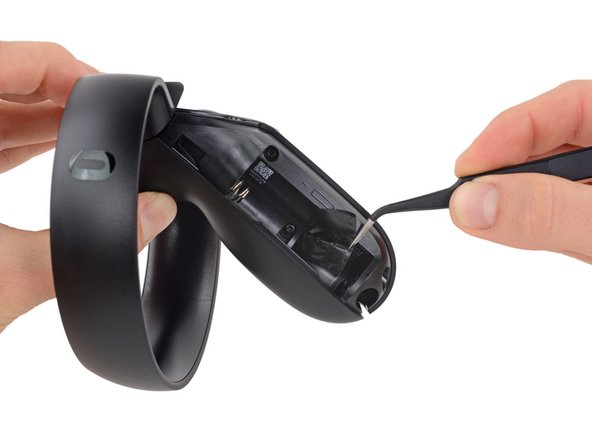
Thanks to a handy "eject" arrow, we're alerted that this Touch controller slides open just like any other remote.
-
The battery panel is secured by a pretty hefty magnet, and packs a rubber bumper to keep the battery nicely in place.
-
Said battery is a non-rechargeable but perfectly standard AA battery, which you can replace with a rechargeable at the first opportunity. Better these than a glued-in battery!
-
This chamber also hosts the model information and point of origin (hello, Dublin!)—plus, we're almost certain there'll be a screw under that sticker.
-
-
-
There are indeed some hidden screws, but even after removing them we're not getting anywhere.
-
Looking around for another point of attack, we decide the top is as good a place as any. Smelling glue, we turn up the heat!
-
Prying up the control surface reveals gobs of glue, and the cause of our troubles: another hidden screw.
-
We may not be inside yet, but things are looking up. The Touch is already previewing some tech for us: switches, a metallic pad, and maybe even the first of many IR LEDs.
-
-
-
-
We're able to remove the final Torx screw with a turn of a Pro Tech Driver.
-
The side panel finally bites the dust, and we get our first real look at the internals.
-
The boards are densely layered inside these handhelds, but we've already got a peek at what might be a
Taptic Enginelinear oscillator?
-
-
-
A few more screws later, the outer rim of the loop is still attached by a bunch of glue, so there's no recourse but to pry again.
-
No heat is required, just prying, as the adhesive is mild-to-medium flavored.
-
Uncovered, the single-cable LED array peels off fairly easily after being disconnected.
-
All 22 IR LEDs are conveniently labeled, and there's even a barcode. Cross your fingers for Oculus-provided replacement parts!
-
-
-
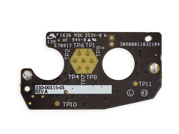
In addition to a handful of passive components, we spy a couple of empty solder pads—perhaps to make custom LED hacks a little quicker.
-
Besides motherboard interconnect and vibrator sockets, we also spy a hexagonal test-point array, accessible from the bottom of the battery caddy.
-
The haptic vibration motor takes a little more work (heat and prying) to extract—it's well-secured with glue.
-
Monolithic Power Systems MP3414DJ 1.8 A synchronous step-up converter
-
-
-
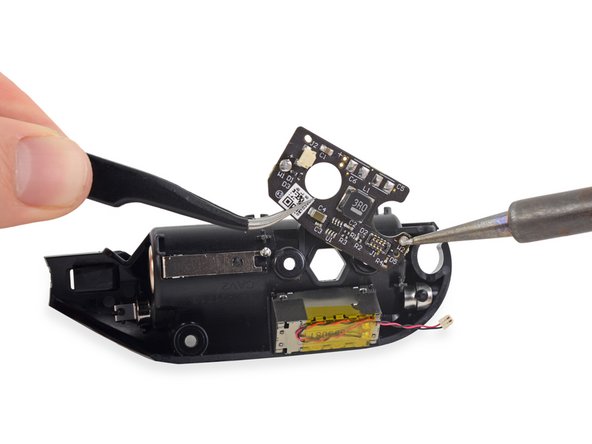
The joystick board appears the be the brains of this operation, it's packed solid with silicon and switches.
-
And two big ol' springs for the XY/AB buttons—probably so they're not too stiff, or too soft, but juuuust right.
-
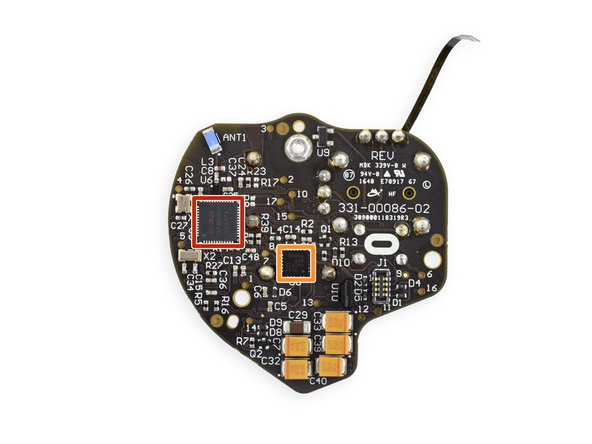
Chips! Some of these guys look oddly familiar ...
-
Nordic Semiconductor nRF51822 Bluetooth Smart and 2.4 GHz proprietary SoC
-
Analog Devices AD7147 single-electrode capacitance sensors controller
-
Invensense MPU-6500 6-axis combo gyroscope and accelerometer
-
Analog Devices (formerly Linear Technology) LT8330 inverting converter w/ 1 A power switch
-
-
-
Last (but not least!), we peel up an action-packed ribbon cable. All told we uncover:
-
Two more IR LEDs—bringing the per-controller total up to 24, the exact number found in the Vive controller.
-
An LED that shines through the top of the controller, presumably as a visible light status LED.
-
A final switch for the Oculus or menu buttons, depending on which controller you're looking at.
-
A spring contact for the conducting pad that turns the "thumb rest" into a capacitive button.
-
- Battery replacements are quick and easy with a magnetic cover being the only barrier to entry.
- There are only T5 and T6 Torx screws in the Touch controllers, making screwdriver selection seamless.
- Accessing the Touch controller internals requires fighting through a thick layer of adhesive.
- The joystick, button bases, and battery connections are soldered directly to a board and require soldering knowledge to repair.
- Navigating through the tabs, adhesive, and hidden screws is not intuitive and could result in damage during disassembly.


Final Thoughts
Repairability Score


(10 is easiest to repair)
18 Comments
The 'Big ol spring' the buttons use is the conductive path for the capacitive sensing for the face buttons.
Could you add an extra shot of the underside of the button housing, so we can see the cam profile the 'grip' trigger uses to modulate spring force?
Agreed, more photos of the housing, analog stick and buttons between step 9 and 10. Thanks!
analog stick broke down where can i find some one to replace it
There are reports of a common problem with the Oculus Touch trigger. With time a rubber dampener will come loose (it is probably only glued) and the trigger will exhibit a loud noise when used. This can occur from anything between a few hours to months of use, depending on how hard/vigorously the trigger is pressed/used. Later squeaking noises may also develop, due to axial play caused by the lack of dampening.
I have tried to locate the rubber dampener from the images provided in the teardown. This is my best guess, but proper verification is needed: