Introduction
One of my LIFX Color 1000 smart lightbulbs has had intermittent connectivity problems since it was installed. The rest of the bulbs have worked very well. After having the troublesome bulb replaced by LIFX, I decided to do a teardown to see what was inside.
In the process I discovered the heatsink was not securely attached, leading me to believe that excess heat was causing the problems. Upon re-assembly I've added a thermal adhesive. I'm optimistic that the bulb may have less trouble - time will tell!
What you need
-
-
The diffuser is held onto the bulb's base by four snap-lock plastic tabs, which also have a dab of silicone adhesive on them to prevent the diffuser from rattling.
-
The tabs are just to the right of the small Phillips-head screws you can see in the small space between the diffuser and base.
-
Insert a strong screwdriver or similar prying tool to bend the plastic tabs. You'll need to bend at least two at once, and then insert something to hold open the one side while you work on the other.
-
-
-
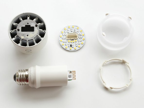
Removing the diffuser exposes the LED PCB. The edge of the WiFi board can also be seen with the antenna protruding.
-
Note the silicone adhesive on the tabs. You probably don't need to replace this with fresh adhesive, but if you do, make sure it's rated for high temperatures.
-
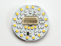
On the LED PCB, you can see the white and colored LEDs. The PCB is a thermally-conductive aluminum material.
-
Around the edge of the bulb's case there is a plastic retaining ring attached by four Phillips-head screws. It's not necessary to remove this for further disassembly.
-
The LED PCB has a pin header that connects down into the WiFi board. A thermal adhesive pad holds the PCB to the metal bulb case. You can gently pry around the edge of the PCB until the adhesive releases, and the connector separates.
-
On my bulb, the PCB was not fully-seated on the thermal pad, potentially causing heat-related intermittent faults.
-
-
-
-
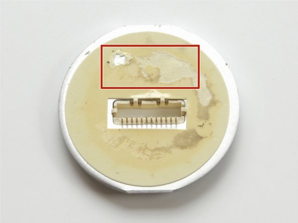
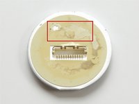
If you compare the under-side of the PCB with the bulb's case, you'll see if the thermal pad was adhered properly.
-
In these photos you can see the pad was only partially attached on one side. The other side of the PCB was lifted several millimeters away from the bulb's base.
-
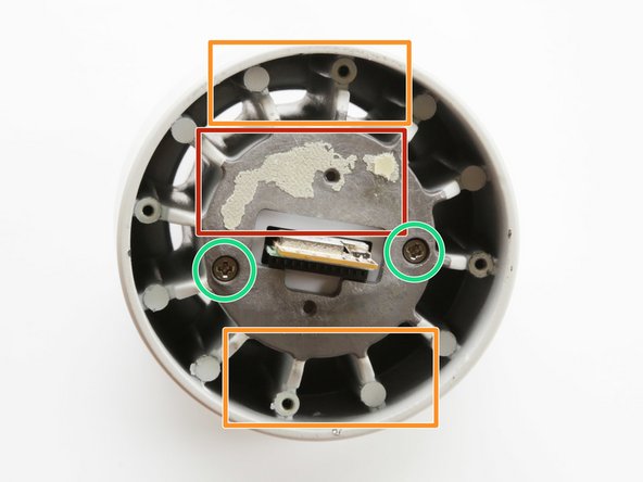
The bulb's metal base serves as a heatsink. You can see the air channels running vertically along the sides. This is why these bulbs should only be installed in a vertical orientation to maintain proper airflow.
-
If you plan to re-assemble the bulb, you should scrape off all the old thermal pad from the PCB and case. Both surfaces should be clean. Replace it with a good thermal adhesive epoxy, following the manufacturer's directions.
-
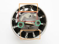
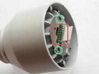
Note the two Phillips-head screws in the central portion of the metal case (marked in green circles). We remove these in the next steps.
-
-
-
Notice the back of the WiFi PCB. There is the female pin-header connector for the LED board, and a series of gold pads for a manufacturing test jig.
-
If you are feeling adventurous, you may be able to find JTAG, serial ports, or other fun hacking opportunities among those pads.
-
If you remove the two screws, the electrical base unit slides out of the metal heatsink case. The electronics are potted and not easily accessible.
-
Re-assembly is the reverse of disassembly.
-


15 Guide Comments
On the last pic, on the wifi board is that a button or a U.fl connector?
Not a U.fl connector, but very similar, with a socket instead of a pin. It's a switched RF test point used during manufacture, like this: http://www.mouser.com/new/murata/muratas... - Basically, you plug in and it disconnects whatever is downstream; in this case, the PCB antenna. So you could certainly use it for your own antenna, but I'm not sure if anyone makes cable connectors per se; it may only be test probes for use in a manufacturing test jig. Can always rip it off and slap on a u.fl instead =)
That switch is on the older model bulb. It's used to reset the configuration if I recall correctly. Turn off, flip switch, turn on, it resets. Something like that!