Introduction
This teardown will show the process of taking a continuity tester apart. A continuity tester is a small electronic device that can be used to test a circuit for its open or closed state. The device operates by connecting the positive and negative leads to a circuit and pressing the small black button. If the red light illuminates, the circuit is closed. If it does not, the circuit is open.
This device was fabricated in a Cal Poly Manufacturing Engineering course. All of the resistors, the switch, the LED, and the IC chip were hand-soldered to the PCB.
What you need
-
-
Not many tools needed here! Just grab your favorite Phillips head screwdriver.
-
The best size for these small screws is a PH1.
-
-
-
Connect the positive and negative leads to each other.
-
Press the small black button
-
Does the red light come on?
-
-
-
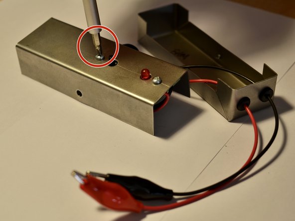
Start with either side of the device and unscrew the Phillips head sheet metal screw.
-
Remove the screw and set aside in a safe place.
-
-
-
Flip over the device to the opposite side and repeat the sheet metal screw removal.
-
-
-
Remove the battery connection on the top of the battery.
-
Set battery aside
-
-
-
-
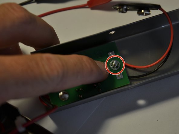
Using the same screwdriver, unscrew one of the top screws that holds in the circuit board.
-
-
-
With the nuts off of the screws, remove the two star washers and set them in your bowl of hardware.
-
-
-
With the nuts and washers off, remove the circuit board from the top shell.
-
-
-
This is a resistor. There are 5 of them on this board!
-
Here we see the LED.
-
This is the Texas Instruments IC Chip. It is the brain of the operation.
-
This is the Panasonic switch.
-
This is a little diode.
-
-
-
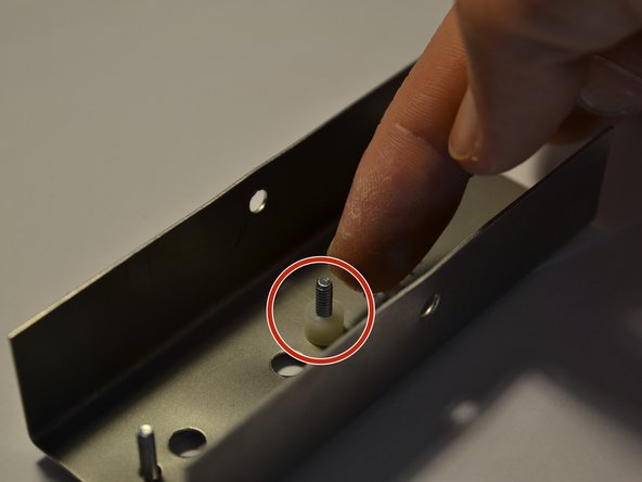
These little spacers keep the circuit board from being smashed against the top shell.
-
Using the best tool (your fingers) remove the first spacers from the screw.
-
-
-
Sit back and observe your hard work.
-
Arrange the parts for a nice pic for your portfolio!
-