Introduction
Follow the steps in this guide to replace the front panel sensor assembly in an iPhone 6s. This component contains the front-facing camera, ambient light sensor, and microphone.
Note that the earpiece speaker is removed in this guide—be sure to save and transfer the earpiece speaker into your replacement cable assembly when you reassemble.
You can also use this guide to replace the earpiece speaker bracket.
What you need
-
-
Remove the two 3.4 mm P2 Pentalobe screws on the bottom edge of the iPhone, on either side of the Lightning connector.
-
-
-
If you don't have an Anti-Clamp, follow the next three steps to use a suction handle.
-
Apply mild heat to the lower edge of the iPhone using an iOpener or hair dryer for about a minute.
-
-
-
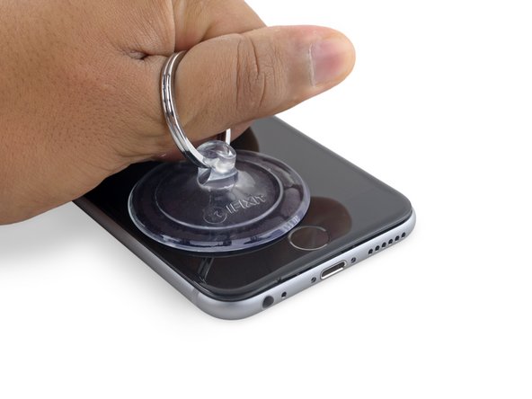
Apply a suction cup to the lower left corner of the display assembly.
-
Take care not to place the suction cup over the home button.
-
-
-
Pull up on the suction cup with firm, constant pressure to create a slight gap between the front panel and rear case.
-
-
-
Place the flat edge of a spudger into the gap between the screen and rear case, directly above the headphone jack.
-
-
-
Twist the spudger to widen the gap between the front panel assembly and the rest of the phone.
-
-
-
Insert the flat end of the spudger on the left side of the phone, between the display assembly and rear case.
-
Slide the spudger up the side of the phone to separate the adhesive and pop the clips free.
-
-
-
Remove the spudger and reinsert it on the bottom edge, where you pried the phone open.
-
Slide the spudger to the right, along the bottom edge of the phone.
-
-
-
Slide the spudger up the right side to continue separating the adhesive and popping the display clips free from the iPhone.
-
-
-
-
Gently grasp the display assembly and lift it up to open the phone, using the clips at the top of the front panel as a hinge.
-
Open the display to about a 90º angle, and lean it against something to keep it propped up while you're working on the phone.
-
Add a rubber band to keep the display securely in place while you work. This prevents undue strain on the display cables.
-
-
-
Remove two Phillips screws securing the battery connector bracket, of the following lengths:
-
One 2.9 mm screw
-
One 2.2 mm screw
-
-
-
Use the point of a spudger to disconnect the battery connector by prying it straight up from the logic board.
-
-
-
Push the battery connector away from the logic board until it stays separated from its socket, so as to avoid any accidental connection to the battery while you work.
-
-
-
Remove the following four Phillips screws securing the display cable bracket:
-
Three 1.2 mm screws
-
One 2.8 mm screw
-
-
-
Use a spudger or a clean fingernail to disconnect the front camera flex cable by prying it straight up from its socket on the logic board.
-
-
-
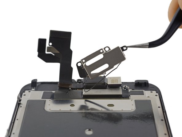
Remove the following three Phillips screws securing the earpiece speaker bracket:
-
Two 2.3 mm screws
-
One 1.9 mm screw
-
-
-
Pull back the front-facing camera to access the earpiece speaker.
-
Remove the earpiece speaker.
-
-
-
Holding the front-facing camera out of the way, use the point of a spudger to push the ambient-light sensor up out of its recess in the front panel.
-
-
-
Use the flat end of a spudger to gently break up the adhesive securing the microphone to the front panel.
-