Introduction
If you have an older HDL-32E Velodyne won't service it: time to DIY. Otherwise what the hell are you doing? This thing isn't cheap, get it serviced.
It isn't that difficult to do, just take your time and be careful.
What you need
-
-
Before you begin, go ahead and get a replacement R4 ZZ ball bearing.
-
You will also need a 3/32nd Allen key or hex driver.
-
Finally, you will need a soldering iron, solder, and maybe some wick
-
Pictured is what is under the top cover. You don't need to remove it but it looks cool so here it is.
-
-
-
There are 4 3/32 hex screws on the bottom of the scanner.
-
Make sure your tool is fairly new, and apply pressure carefully to avoid stripping these screws.
-
Once the screws have been removed, carefully pull the cover off until you have access to the wire connector on the board. You will have to use some force to overcome a large o-ring when pulling the cover off.
-
Unclip the connector and set aside the cover and the packet of silica gel inside. It is a good idea to make sure the gel is dry: bake it in the oven at 275F for an hour or two.
-
-
-
Desolder the five wires going to the encoder sensor. They are white and are glued together. You don't need to label them because they do not cross each other on their way to the board.
-
Desolder the two copper coloured wires next to the thicker wires going to the motor stator. Make sure to label which wire goes where.
-
Pictured is the bottom PCB.
-
-
-
-
In general, try to touch the grounding points on the board before any other parts to avoid damaging it with ESD.
-
There are four 3/32nd hex screws holding the board to the bearing housing. Remove them and set them aside
-
Carefully pull the board up (taking care to mind the gyros) and use the stiff motor wires to hold it off the bearing housing.
-
-
-
In order to remove the bearing housing, you will need to remove the encoder sensor.
-
It is attached with two hex screws. They should be easy to remove (remember that when you are putting it back together).
-
Slide the sensor out radially minding the encoder ring it straddles.
-
Pictured is the assembly with the encoder sensor removed
-
-
-
There are four 3/32nd hex screws holding the bearing housing on. Remove them.
-
There is also a washer and retaining ring on the shaft. Pry the ring off and remove the washer. Take care not to damage the coil sitting in the end of the shaft.
-
Pull the bearing housing up until you can get a screwdriver between it and the main body. Pry it the rest of the way off.
-
Pictured is what it under the bearing housing
-
-
-
From the bottom of the bearing housing, push the bearing out. It shouldn't require that much force.
-
There is a spring underneath the bearing, make sure you don't lose it when you remove the bearing
-
Pictured is the underside of the rear bearing housing. Push the bearing out from this side. Note that the black ring is quite brittle, so take can not to damage it.
-
-
-
The top bearing is an 6002H SS sealed ball bearing. To access it you will have to remove the encoder ring, motor rotor, and motor stator.
-
Before you can removed anything else, you will have to desolder two more wires. Refer to the picture in step six. The wires to desolder are those that pass down through that yellow disc into the shaft. You want them free to pull through the yellow disc.
-
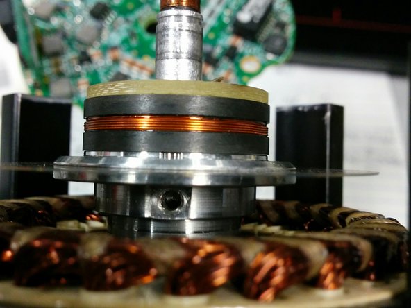
Pictured is a hex key that holds the encoder/induction thing onto the shaft. There are two installed on top of each other (probably for locking). Remove both and set aside. You probably want to mark or think of a way to remember the orientation of the encoder disk on the shaft.
-
Next remove the pieces that hold down the motor stator. There are four distributed around the stator, and each has two hex screws. You should mark the stator somehow so that it goes back in the same spot.
-
Now carefully pry the motor stator and remove it and the encoder/induction thing/permanent magnet assembly on the main shaft. Due to the strong magnets, I found it easiest to remove the shaft assembly and motor stator together.
-
At this point, the top bearing should be exposed. Use a bearing puller or press to remove it and replace it. Refer to last picture for image with everything removed. Note that I did not replace the top bearing, so while it will probably work I can't personally vouch for it.
-


To reassemble your device, follow these instructions in reverse order.
To reassemble your device, follow these instructions in reverse order.
Cancel: I did not complete this guide.
2 other people completed this guide.
