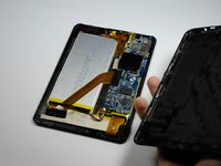
Trio Stealth G4 Motherboard Replacement

What you need

  1. Trio Stealth G4 Motherboard Replacement, Back Panel: step 1, image 1 of 1
    • Working on your device while it is turned on may result in electric shock. Be sure to shut down and unplug your device before you begin.

    • Flip your tablet over so that the back panel is facing up.

  2. Trio Stealth G4 Motherboard Replacement: step 2, image 1 of 2 Trio Stealth G4 Motherboard Replacement: step 2, image 2 of 2
    • Use a plastic opening tool to gently pry the back panel assembly apart from the front casing.

    • Start on one edge of the device by inserting the plastic opening tool between the back panel and the front casing using a gentle rocking motion.

  3. Trio Stealth G4 Motherboard Replacement: step 3, image 1 of 1
    • Once you have successfully separated one edge of the back panel from the front casing, slide the plastic opening tool along the other edges to detach them as well.

    • The latches keeping the back panel attached to the front casing can sometimes be a little difficult to separate, so don't be afraid to use some force.

  4. Trio Stealth G4 Motherboard Replacement: step 4, image 1 of 2 Trio Stealth G4 Motherboard Replacement: step 4, image 2 of 2
    • Remove the back panel from the rest of the tablet and set it aside.

  5. Trio Stealth G4 Motherboard Replacement: step 5, image 1 of 1
    • The plastic volume button cover may fall out when you remove the back panel. Set it aside.

  6. Trio Stealth G4 Motherboard Replacement, Motherboard: step 6, image 1 of 3 Trio Stealth G4 Motherboard Replacement, Motherboard: step 6, image 2 of 3 Trio Stealth G4 Motherboard Replacement, Motherboard: step 6, image 3 of 3
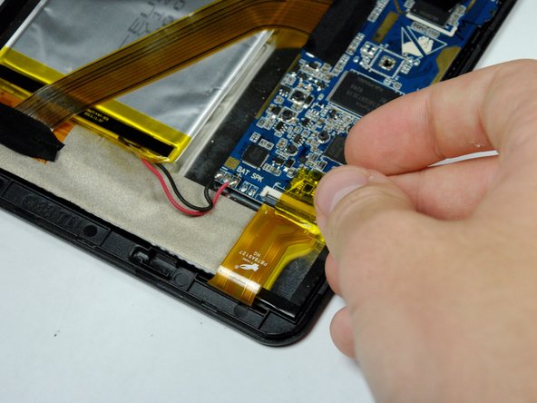
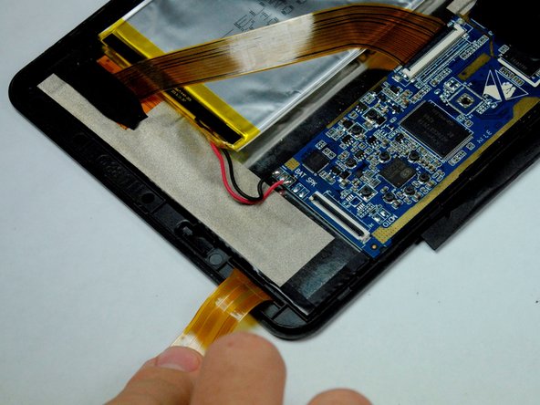
    • Remove the 4 pieces of tape covering the zero insertion force (ZIF) connectors on the motherboard.

  7. Trio Stealth G4 Motherboard Replacement: step 7, image 1 of 3 Trio Stealth G4 Motherboard Replacement: step 7, image 2 of 3 Trio Stealth G4 Motherboard Replacement: step 7, image 3 of 3
    • Use a spudger to flip up the black flaps on each of the 4 ZIF connectors.

    • Once the flaps are up, use your fingers to disconnect the end of the ribbon wires from the connectors.

  8. Trio Stealth G4 Motherboard Replacement: step 8, image 1 of 2 Trio Stealth G4 Motherboard Replacement: step 8, image 2 of 2
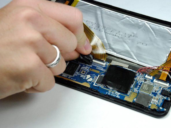
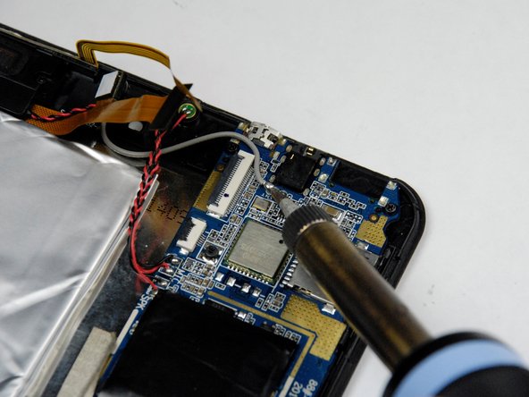
    • Use the soldering iron to melt away the solder from each of the wires connecting to the motherboard.

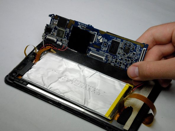
    • Once the solder is completely removed, pull the wires away from the motherboard.

  9. Trio Stealth G4 Motherboard Replacement: step 9, image 1 of 2 Trio Stealth G4 Motherboard Replacement: step 9, image 2 of 2
    • Use a J00 Phillips head screwdriver to remove the two 4.3 mm screws securing the motherboard to the device and set them aside.

  10. Trio Stealth G4 Motherboard Replacement: step 10, image 1 of 1
    • Remove the silver piece of tape from the left edge of the motherboard.

  11. Trio Stealth G4 Motherboard Replacement: step 11, image 1 of 2 Trio Stealth G4 Motherboard Replacement: step 11, image 2 of 2
    • Use a spudger to lift the motherboard from the device.

Conclusion

To reassemble your device, follow these instructions in reverse order.

One other person completed this guide.

Matt Arnold

Member since: 09/22/15

607 Reputation

5 Guides authored

Team

Baylor, Team 4-1, Williams Fall 2015 Member of Baylor, Team 4-1, Williams Fall 2015

BU-WILLIAMS-F15S4G1

4 Members

10 Guides authored

0 Comments

Add Comment

View Statistics:

Past 24 Hours: 0

Past 7 Days: 0

Past 30 Days: 0

All Time: 891