
Sanyo VPC S1275 Flash Mechanism Replacement

What you need

  1. Sanyo VPC S1275 Flash Mechanism Replacement, Case: step 1, image 1 of 3 Sanyo VPC S1275 Flash Mechanism Replacement, Case: step 1, image 2 of 3 Sanyo VPC S1275 Flash Mechanism Replacement, Case: step 1, image 3 of 3
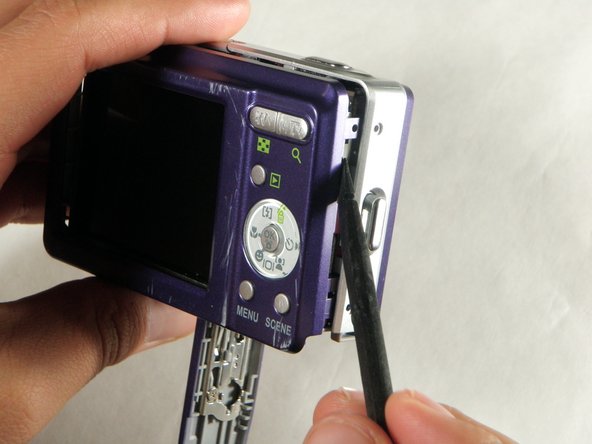
    • Remove the following six screws using the Phillips #00 screwdriver:

    • Two screws on the left side of the camera.

    • Two screws on the right side of the camera.

    • Two screws on the bottom of the camera.

  2. Sanyo VPC S1275 Flash Mechanism Replacement: step 2, image 1 of 2 Sanyo VPC S1275 Flash Mechanism Replacement: step 2, image 2 of 2
    • Open the battery slot on the bottom of the camera by sliding the door to the right.

    • Remove the single 4 mm screw on the bottom right using the Phillips #00 screwdriver.

  3. Sanyo VPC S1275 Flash Mechanism Replacement: step 3, image 1 of 3 Sanyo VPC S1275 Flash Mechanism Replacement: step 3, image 2 of 3 Sanyo VPC S1275 Flash Mechanism Replacement: step 3, image 3 of 3
    • Insert a spudger in the seam at the bottom of the camera.

    • Gently separate the rear case from the front of the camera.

  4. Sanyo VPC S1275 Flash Mechanism Replacement: step 4, image 1 of 1
    • This step is only needed for the case and logic board replacement

    • Using the Phillips #00 screwdriver, remove the single screw attached to the front casing in the top left corner. The front case should easily separate.

  5. Sanyo VPC S1275 Flash Mechanism Replacement: step 5, image 1 of 1
    • This step is only needed for the case replacement.

    • Using the Phillips #00 screwdriver, remove the screw on the inside of the battery door.

    • Slide the battery door off of the hinge.

  6. Sanyo VPC S1275 Flash Mechanism Replacement, LCD Screen: step 6, image 1 of 2 Sanyo VPC S1275 Flash Mechanism Replacement, LCD Screen: step 6, image 2 of 2
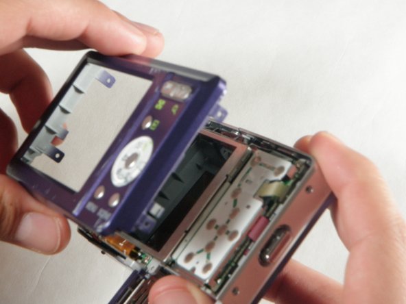
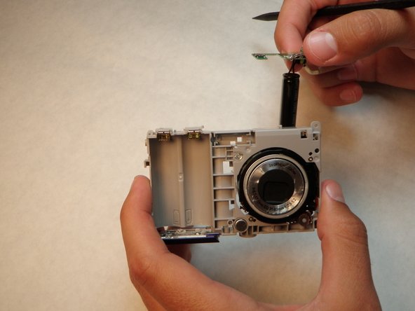
    • Using the spudger, carefully lift up the LCD screen, making sure to keep the ribbon cable intact.

    • Place the LCD screen on a non-abrasive surface.

  7. Sanyo VPC S1275 Flash Mechanism Replacement: step 7, image 1 of 1
    • Using the spudger lift the black flap up to release the ribbon cable.

    • The LCD screen will now be completely detached from the camera.

  8. Sanyo VPC S1275 Flash Mechanism Replacement, Logic Board: step 8, image 1 of 1
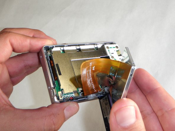
    • Using the Phillips #00 screwdriver, remove the four screws on the outer edge of the LCD holding plate.

  9. Sanyo VPC S1275 Flash Mechanism Replacement: step 9, image 1 of 1
    • Be careful when rotating the plate in the next step to prevent the ribbon cable in the top right from ripping.

    • Using your right hand, grab the left side of the LCD holding plate and rotate it to the right.

  10. Sanyo VPC S1275 Flash Mechanism Replacement: step 10, image 1 of 1
    • Remove the ribbon cable from its slot by gently pulling the LCD holding plate to the right.

  11. Sanyo VPC S1275 Flash Mechanism Replacement: step 11, image 1 of 2 Sanyo VPC S1275 Flash Mechanism Replacement: step 11, image 2 of 2
    • Do not touch ANY part of the logic board previously covered by the black film until the capacitor has been completely discharged. This camera has a 330V, 100 µF capacitor which can cause painful electric shock.

    • Using the spudger (or any non-metal prying tool), gently remove the black film.

  12. Sanyo VPC S1275 Flash Mechanism Replacement: step 12, image 1 of 1
    • Using the capacitor discharge tool carefully touch each end of the capacitor discharge tool to the each terminal of the capacitor.

    • Click the link below for instructions on how to make the capacitor discharge tool: Constructing a Capacitor Discharge Tool

    • NEVER touch both both capacitor terminals with just one of the wires. This will create a potentially dangerous large spark. This will also cause serious damage to the camera.

    • Keep the wires connected to the capacitor terminals for 2 minutes to completely discharge the capacitor.

    • The camera should be completely safe to handle now.

  13. Sanyo VPC S1275 Flash Mechanism Replacement: step 13, image 1 of 1
    • Touch the hot tip of the solding iron to the first solder connecting the flash mechanism to the logic board until the solder melts.

    • Repeat this for the next 10 solders.

    • Verify solders have detached logic board.

  14. Sanyo VPC S1275 Flash Mechanism Replacement: step 14, image 1 of 1
    • Touch the hot soldering iron to the solder in the lower left corner connecting the logic board to the red wire.

    • When the solder has completely melted, gently pull the wire free from the logic board.

    • Repeat for the red, blue, and then black wires.

  15. Sanyo VPC S1275 Flash Mechanism Replacement: step 15, image 1 of 2 Sanyo VPC S1275 Flash Mechanism Replacement: step 15, image 2 of 2
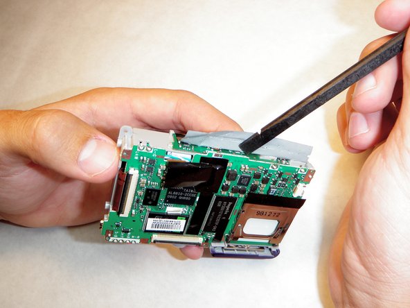
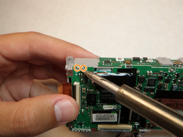
    • Touch the soldering iron tip to the solder in the upper right corner connecting the logic board to the battery lead.

    • Pull the battery lead out of the slot in the logic board. This must be done immeadiately after the solder melts.

    • Repeat for the solder to the left.

    • The logic board will now be completely free from the camera.

  16. Sanyo VPC S1275 Flash Mechanism Replacement: step 16, image 1 of 1
    • Insert the battery leads into the slots in the new logic board.

    • Solder both leads to the logic board.

  17. Sanyo VPC S1275 Flash Mechanism Replacement, Flash Mechanism: step 17, image 1 of 1
    • Remove screw from top of the flash mechanism

  18. Sanyo VPC S1275 Flash Mechanism Replacement: step 18, image 1 of 1
    • Remove the flash bulb from the camera housing by gently pulling on the wires with a pair of tweezers.

  19. Sanyo VPC S1275 Flash Mechanism Replacement: step 19, image 1 of 1
    • Poke the capacitor out of its housing with the spudger.

  20. Sanyo VPC S1275 Flash Mechanism Replacement: step 20, image 1 of 2 Sanyo VPC S1275 Flash Mechanism Replacement: step 20, image 2 of 2
    • Break the tabs on the camera housing that hold the flash logic board.

    • Lift up on the logic board. The capacitor and the flash bulb will be removed as well.

Conclusion

To reassemble your device, follow these instructions in reverse order.

Evan Perez

Member since: 04/15/10

19 Reputation

2 Guides authored

Team

Cal Poly, Team 24-24, Regan Spring 2010 Member of Cal Poly, Team 24-24, Regan Spring 2010

CPSU-REGAN-S10S24G24

4 Members

12 Guides authored

0 Comments

Add Comment

View Statistics:

Past 24 Hours: 0

Past 7 Days: 0

Past 30 Days: 4

All Time: 3,009