Mitsubishi WD57734 DLP Chip Replacement

What you need

  1. Mitsubishi WD57734 DLP Chip Replacement, Back Panel: step 1, image 1 of 2 Mitsubishi WD57734 DLP Chip Replacement, Back Panel: step 1, image 2 of 2
    • Remove the following 8 Phillips #1 screws:

    • One 22 mm Phillips #1 in the bottom right corner of the back panel.

    • One 18 mm Phillips #1 in the top middle of the back panel.

    • Six 18 mm Phillips #1 in the rest of the back panel.

  2. Mitsubishi WD57734 DLP Chip Replacement: step 2, image 1 of 1
    • Pull the back panel off of the television by gripping the sides and rotating it down.

  3. Mitsubishi WD57734 DLP Chip Replacement, DLP Chip: step 3, image 1 of 2 Mitsubishi WD57734 DLP Chip Replacement, DLP Chip: step 3, image 2 of 2
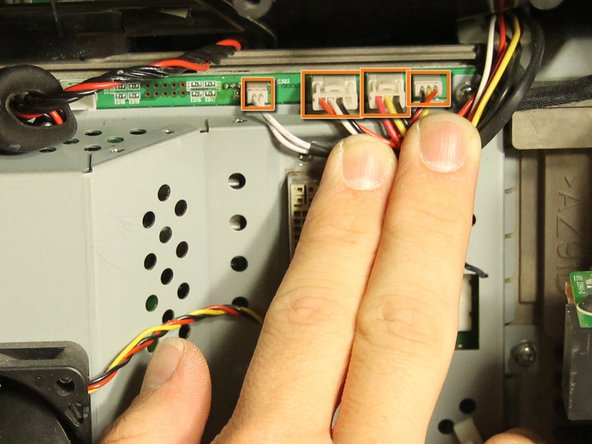
    • Disconnect the light engine power cable by holding its white tab and pulling straight back.

    • Disconnect the four connections above the black data connection by gently pulling the plugs out of the sockets (some of the connections have a tab that must be pressed when pulling to disconnect).

  4. Mitsubishi WD57734 DLP Chip Replacement: step 4, image 1 of 2 Mitsubishi WD57734 DLP Chip Replacement: step 4, image 2 of 2
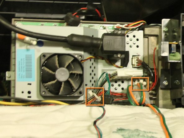
    • Disconnect lamp ballast power and data connections in front of the light engine by pressing their corresponding tabs and pulling them apart.

    • Release the cables from the white cable ties by twisting the white cable clasps and pulling the cables out of the clasps.

  5. Mitsubishi WD57734 DLP Chip Replacement: step 5, image 1 of 1
    • Loosen the two secured Phillips #00 screws securing the black data connection to the light engine.

    • These two screws are attached to the connector and are not meant to be removed completely.

    • Gently pull the black connector off the light engine.

  6. Mitsubishi WD57734 DLP Chip Replacement: step 6, image 1 of 1
    • Use pliers to remove the two securing bolts from above and below the data port by rotating counterclockwise.

    • Remove the seven 8 mm Phillips #0 screws holding the plate to the light engine board.

    • Gently hold each side of the metal frame and pull it straight back to reveal the board and heat sinks underneath.

  7. Mitsubishi WD57734 DLP Chip Replacement: step 7, image 1 of 1
    • Disconnect the last connection from the light engine by holding the white tab and pulling straight back.

  8. Mitsubishi WD57734 DLP Chip Replacement: step 8, image 1 of 1
    • Remove the two 15 mm Phillips #0 screws holding the DLP heat sink to the light engine board.

    • Springs underneath the screws help hold the heat sink on top of the DLP chip. During reassembly do not tighten the screws down all the way. Doing so can damage the DLP chip.

  9. Mitsubishi WD57734 DLP Chip Replacement: step 9, image 1 of 1
    • Remove the five remaining 8 mm Phillips #0 screws.

  10. Mitsubishi WD57734 DLP Chip Replacement: step 10, image 1 of 1
    • Carefully pull the board to expose the two cables that connect to the back of the board.

    • Use pliers and tweezers to disconnect the ribbon cable by pulling it straight out of its socket and the data connector by holding its tab and pulling it straight back from the board.

    • Do not let the ribbon cable recede into the light engine.

    • Replacing the ribbon cable is the hardest step when you reassemble. You'll need to align the board with the bolt holes, and using fingers or tweezers line the ribbon with the slot (which you can't see) and push fairly hard to mate the connector. This cable goes to the color wheel. Be careful not to flip it upside down.

    • Tip: Plugging the holes with some painter's tape may make it harder for the wires to slip into the light engine once detached.

  11. Mitsubishi WD57734 DLP Chip Replacement: step 11, image 1 of 2 Mitsubishi WD57734 DLP Chip Replacement: step 11, image 2 of 2
    • Lay the board facedown on a smooth surface.

    • Do not touch front of the dlp chip. Oils or dust will distort the tv image.

    • Use a small flathead screwdriver to turn the locking screw half a turn counterclockwise.

    • Remove DLP chip from the light engine board by pulling it straight back.

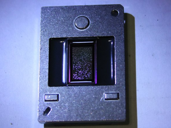
    • The photo shows an example of a broken DLP chip with hundreds of stuck pixels.

  12. Mitsubishi WD57734 DLP Chip Replacement: step 12, image 1 of 1
    • During reassembly after installing the new DLP chip, it is recommended that you remove the old thermal paste from the DLP heat sink with a thermal compound remover and purifier.

    • After removing the thermal compound, apply a small amount of new thermal compound (about the size of a grain of rice) and use a card to apply it evenly over the surface of the heat sink that will be in contact with the chip. This will improve the cooling of the chip during use and will prevent overheating that caused failure of the old chip.

David Sylvester

Member since: 10/02/12

228 Reputation

1 Guide authored

Team

Cal Poly, Team 18-39, Regan Fall 2012 Member of Cal Poly, Team 18-39, Regan Fall 2012

CPSU-REGAN-F12S18G39

4 Members

6 Guides authored

View Statistics:

Past 24 Hours: 0

Past 7 Days: 1

Past 30 Days: 14

All Time: 19,632