Introduction
Use this guide to replace the Logic Board in your MacBook Pro 15" Retina Display Mid 2015.
Don't forget to clean and re-apply thermal paste if you remove the heat sink. Follow this guide to learn how.
What you need
-
-
Remove the following P5 pentalobe screws securing the lower case to the MacBook Pro:
-
Eight 3.1 mm
-
Two 2.3 mm
-
-
-
Gently lift each side of the battery connector to pry the connector out of its socket on the logic board.
-
Bend the connector back toward the battery, ensuring that the battery connector doesn't accidentally make contact with the logic board.
-
-
-
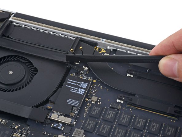
Use a spudger or tweezers to pry the three AirPort antenna cables straight up off of their sockets on the AirPort board, and bend them up and out of the way.
-
-
-
Use the tip of a spudger to push the camera cable connector out of its socket on the logic board.
-
-
-
Use your fingers to pull the AirPort/Camera cables up off the fan.
-
Carefully de-route the cables from the plastic cable guide.
-
-
-
Remove the four 2.2 mm T5 Torx screws securing the I/O board cable connector covers.
-
-
-
Remove the left connector cover.
-
Use the flat end of a spudger to pry the left end of the I/O board cable up from its socket on the logic board.
-
-
-
Remove the right connector cover.
-
Use the flat end of a spudger to pry the right end of the I/O board cable up from its socket on the logic board.
-
-
-
Use a T5 Torx driver to remove the following three screws securing the right fan to the logic board:
-
One 5.0 mm screw with a 2.0 mm long shoulder
-
One 4.0 mm screw with a wide head
-
One 4.4 mm screw
-
-
-
Use the tip of a spudger to flip up the retaining flap on the right fan ribbon cable ZIF socket.
-
-
-
Lift the fan and push it gently towards the back edge of the MacBook to free the fan cable from its socket.
-
Remove the fan.
-
-
-
-
Remove the following three screws securing the left fan to the logic board:
-
One 3.6 mm T5 Torx screw with a wide head
-
One 5.0 mm T5 Torx screw with a 2.0 mm long shoulder
-
One 4.4 mm T5 Torx screw
-
-
-
Use the tip of a spudger to flip up the retaining flap on the left fan ribbon cable ZIF socket.
-
-
-
Lift the fan and push it gently towards the back edge of the MacBook to free the fan cable from its socket.
-
Remove the fan.
-
-
-
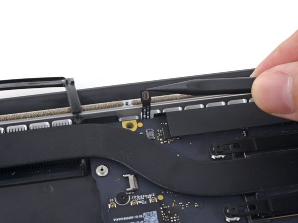
Lift the end of the SSD up enough to pass over the speaker directly behind it.
-
Pull the SSD straight out of its socket on the logic board.
-
-
-
Use the point of a spudger to flip up the locking mechanism on the I/O board connector.
-
Flip the spudger around and use the flat end to slide the I/O cable out of the connector.
-
-
-
Slightly lift the interior edge of the I/O board and pull it toward the center of the MacBook, away from the side of the case.
-
Remove the I/O board.
-
-
-
Remove the two 2.2 mm Torx T5 screws securing the touchpad cable connector cover to the logic board.
-
Remove the cover.
-
-
-
Use the flat end of a spudger to disconnect the touchpad cable connector from its socket in the logic board.
-
-
-
Remove the following six screws securing the logic board assembly to the upper case.
-
One 3.8 mm T5 Torx screw
-
Two 5.7 mm T5 Torx screws
-
One 5.6 mm T5 Torx screw (this one is silver and has a taller head than the others)
-
One 2.6 mm T5 Torx screw
-
One 3.2 mm T5 Torx screw
-
-
-
The following steps will detail disconnecting these six connectors. Be sure to read each step, as these connectors come in different styles that disconnect differently.
-
Microphone cable
-
Left speaker cable
-
Keyboard data cable
-
Right speaker cable
-
Keyboard backlight cable
-
Display data cable
-
-
-
Use the tip of a spudger to flip up the retaining flap on the microphone ribbon cable ZIF socket.
-
Pull the microphone ribbon cable out of its socket, parallel to the logic board.
-
-
-
Use the flat end of a spudger to pry the left speaker connector up and out of its socket on the logic board.
-
Gently fold the cable up and out of the way of the logic board.
-
-
-
Use the tip of a spudger to flip up the retaining flap on the keyboard data cable ZIF socket.
-
Pull the keyboard data cable out of its ZIF socket. Be sure to pull parallel to the logic board, and not straight up.
-
-
-
Use the tip of a spudger to pry the right speaker connector up and out of its socket on the logic board.
-
Gently fold the cable up and out of the way of the logic board.
-
-
-
Use the point of a spudger to pry the keyboard backlight connector up from its socket on the logic board.
-
-
-
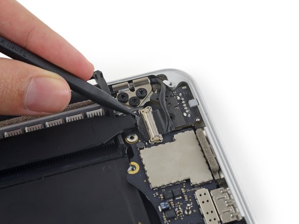
Use the tip of a spudger to flip up the display data cable lock and rotate it toward the MagSafe 2 power port side of the computer.
-
-
-
Pull the display data cable straight out of its socket on the logic board.
-
Gently bend the display data cable toward the display hinge, to expose the screws on the MagSafe 2 board.
-
-
-
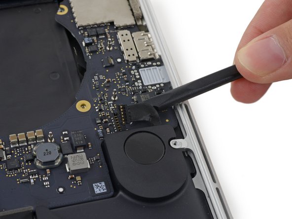
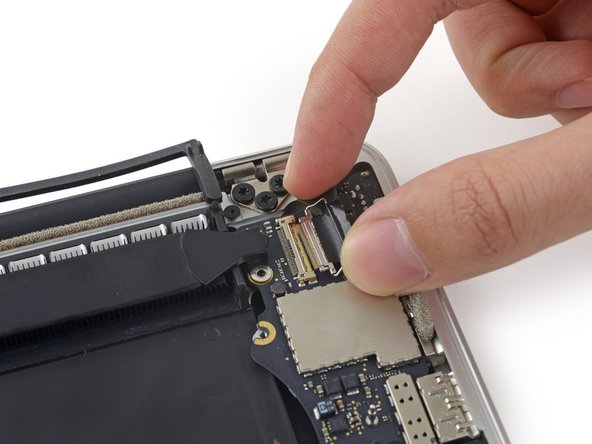
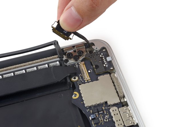
Use the tip of a spudger to flip up the metal retaining flap on the HDMI data transfer cable.
-
Gently pull the HDMI data transfer cable straight out of its socket on the logic board.
-
-
-
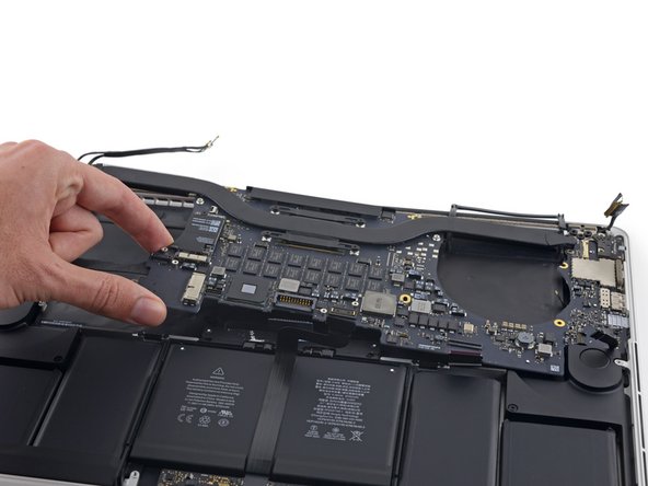
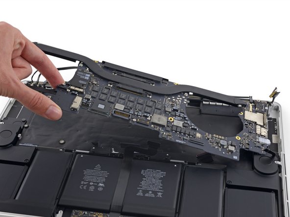
Lift the end of the AirPort board up enough to pass over the heat sink directly behind it.
-
Pull the AirPort board straight out of its socket on the logic board.
-
-
-
Remove the four 3.4 mm T5 Torx screws from the heat sink brackets.
-
Remove the heat sink brackets.
-
-
-
Remove the heat sink.
-
On reassembly, be sure to clean the CPU and heat sink and reapply thermal compound to the CPU. Follow this guide to learn how.
-