Introduction
Use this guide to replace a faulty logic board.
Don't forget to follow our thermal paste application guide before you reinstall your heat sink.
What you need
-
-
Remove the following ten screws securing the lower case to the upper case:
-
Two 2.3 mm P5 Pentalobe screws
-
Eight 3.0 mm P5 Pentalobe screws
-
-
-
Wedge your fingers between the upper case and the lower case.
-
Gently pull the lower case away from the upper case to remove it.
-
-
-
Use the flat end of a spudger to lift the battery connector straight up out of its socket on the logic board.
-
-
-
Remove the following screws securing the heat sink to the logic board:
-
One 2.7 mm T5 screw (silver)
-
Four T5 screws (black)
-
-
-
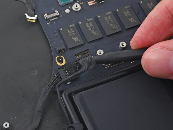
Use the tip of a spudger to push on either side of the the iSight camera cable connector to walk it out of its socket on the logic board.
-
-
-
-
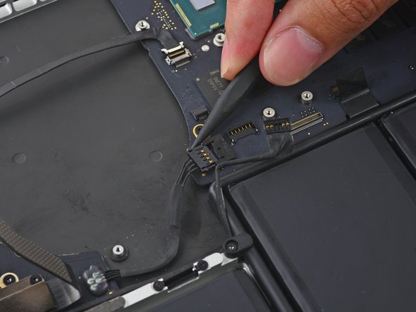
Use the tip of a spudger to flip the tab on the fan's ZIF connector.
-
Carefully pull the fan cable straight out of its socket.
-
-
-
Remove the following screws securing the fan to the upper case:
-
One 5.0 mm T5 Torx screw
-
Two 3.6 mm T5 Torx screws
-
-
-
Lift the end of the fan closest to the display hinge and remove the fan from the upper case.
-
-
-
Remove the two 2.1 mm T5 Torx screws securing the I/O board cable bracket to the logic board.
-
Remove the I/O board cable bracket.
-
-
-
Use the flat end of a spudger to pop the I/O board connector straight up off its socket on the logic board.
-
-
-
Use the tip of a spudger to lift the right speaker connector straight up out of its socket on the logic board.
-
-
-
With the tip of a spudger, push on either side of the I/O board connector to walk it out of its socket on the logic board.
-
-
-
Use the flat end of a spudger to disconnect the keyboard backlight cable and bend it up out of the way of the logic board.
-
-
-
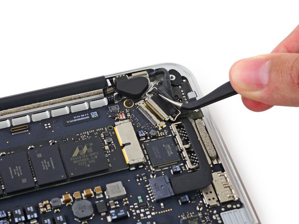
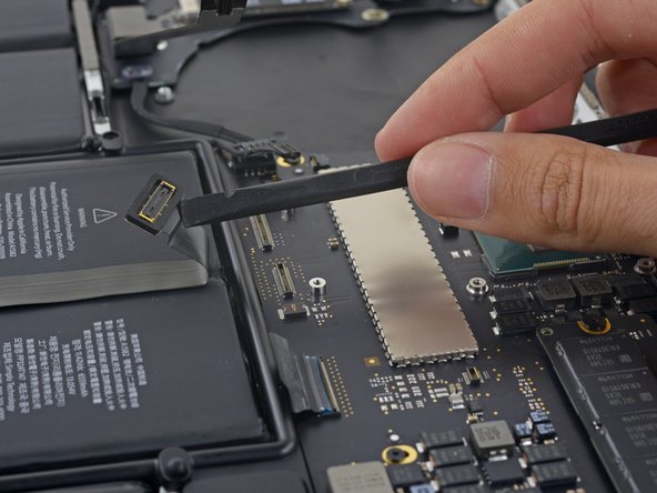
Grab the black plastic tab to flip the display cable connector open and pull it straight out of its socket on the logic board.
-
-
-
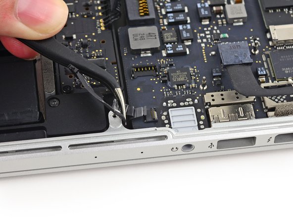
Wedge the flat end of a spudger under the left speaker cable near the connector and lift it straight up out of its socket and fold it out of the way.
-
-
-
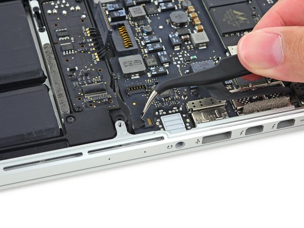
Use the tip of a spudger to flip the retaining tab on the microphone cable ZIF connector.
-
Pull the microphone cable out of its socket on the logic board.
-
-
-
Use the flat end of a spudger to pop the trackpad connector straight up off its socket on the logic board.
-
Fold the cable out back over the battery to clear the way for the logic board.
-
-
-
Lift the processor end of the logic board up slightly and pull it toward the fan recess to free the ports from the edge of the upper case.
-
Remove the logic board.
-
-
-
Lift the free end of the SSD up slightly and pull it straight out of its socket on the logic board.
-