
MacBook Air 13" Mid 2011 Logic Board Replacement

What you need

  1. MacBook Air 13" Mid 2011 Logic Board Replacement, Lower Case: step 1, image 1 of 1
    Tool used on this step:
    P5 Pentalobe Screwdriver Retina MacBook Pro and Air
    $5.99
    Buy
    • Before proceeding, power down your MacBook. Close the display and lay it on a soft surface, top-side down.

    • Use a P5 Pentalobe driver to remove ten screws securing the lower case, of the following lengths:

    • Two 9 mm screws

    • Eight 2.6 mm screws

  2. MacBook Air 13" Mid 2011 Logic Board Replacement: step 2, image 1 of 1
    • Wedge your fingers between the display and the lower case and pull upward to pop the lower case off the Air.

    • Remove the lower case and set it aside.

  3. MacBook Air 13" Mid 2011 Logic Board Replacement, Battery Connector: step 3, image 1 of 2 MacBook Air 13" Mid 2011 Logic Board Replacement, Battery Connector: step 3, image 2 of 2
    • As a precaution against accidental discharge or shock, disconnect the battery connector from the logic board.

    • Grab the clear plastic pull tab attached to the battery connector and pull it toward the front edge of the Air to disconnect the battery from the logic board.

    • Be sure to pull the connector horizontally toward the battery, and not straight up from the Air, or you may damage the socket on the logic board.

  4. MacBook Air 13" Mid 2011 Logic Board Replacement, I/O Board Cable: step 4, image 1 of 1
    • Use the flat end of a spudger to pry the I/O board cable connector upward out of its socket on the I/O board.

  5. MacBook Air 13" Mid 2011 Logic Board Replacement: step 5, image 1 of 1
    • Carefully peel the I/O board cable from the top of the fan.

  6. MacBook Air 13" Mid 2011 Logic Board Replacement: step 6, image 1 of 2 MacBook Air 13" Mid 2011 Logic Board Replacement: step 6, image 2 of 2
    • The following connector has an especially deep socket. Use care when disconnecting it.

    • While gently pulling the I/O board cable upward near its connection to the logic board, use the tip of a spudger to pry upward on alternating sides of the connector to help "walk" it out of its socket.

    • Remove the I/O board cable.

  7. MacBook Air 13" Mid 2011 Logic Board Replacement, Fan: step 7, image 1 of 1
    • Use the tip of a spudger to carefully flip up the retaining flap on the fan cable ZIF socket.

    • Be sure you are prying up on the hinged retaining flap, not the socket itself.

  8. MacBook Air 13" Mid 2011 Logic Board Replacement: step 8, image 1 of 1
    • Peel the rubber gasket off the adhesive on the top of the fan.

  9. MacBook Air 13" Mid 2011 Logic Board Replacement: step 9, image 1 of 1
    • Remove the following three screws securing the fan to the upper case:

    • One 3.6 mm T5 Torx screw

    • One 2.7 mm T5 Torx screw

    • One 3.6 mm T5 Torx screw with a short head

  10. MacBook Air 13" Mid 2011 Logic Board Replacement: step 10, image 1 of 1
    • Lift the fan out of the upper case and carefully pull the fan ribbon cable out of its socket as you remove it from the Air.

  11. MacBook Air 13" Mid 2011 Logic Board Replacement, I/O Board: step 11, image 1 of 1
    • Disconnect the I/O board by pulling the power cable away from its socket on the logic board.

    • Pull the cable parallel to the face of the logic board toward the right edge of the Air.

  12. MacBook Air 13" Mid 2011 Logic Board Replacement: step 12, image 1 of 1
    • Pull the camera cable parallel to the face of the I/O board toward the corner of the Air to disconnect it from its socket, using the tip of a spudger to help push the connector out of its socket.

    • Do not lift upward on this cable as you disconnect it, as its socket may break off the logic board.

  13. MacBook Air 13" Mid 2011 Logic Board Replacement: step 13, image 1 of 2 MacBook Air 13" Mid 2011 Logic Board Replacement: step 13, image 2 of 2
    • Use the flat end of a spudger to pry the left speaker cable connector up and out of its socket on the I/O board.

    • Pry up from beneath the wires.

    • De-route the left speaker cable from its retainer on the I/O board.

  14. MacBook Air 13" Mid 2011 Logic Board Replacement: step 14, image 1 of 1
    • Use the flat end of a spudger to pry the microphone cable connector up and out of its socket on the I/O board.

    • Pry up from beneath the wires.

  15. MacBook Air 13" Mid 2011 Logic Board Replacement: step 15, image 1 of 1
    • Remove the single 3.6 mm T5 Torx screw securing the I/O board to the upper case.

  16. MacBook Air 13" Mid 2011 Logic Board Replacement: step 16, image 1 of 1
    • Carefully lift the I/O board from its edge nearest the logic board and remove it from the upper case.

  17. MacBook Air 13" Mid 2011 Logic Board Replacement, Battery: step 17, image 1 of 1
    • Remove the following five screws securing the battery to the upper case:

    • Three 6.3 mm T5 Torx screws

    • Two 2.4 mm T5 Torx screws

  18. MacBook Air 13" Mid 2011 Logic Board Replacement: step 18, image 1 of 1
    • When handling the battery, avoid squeezing or touching the four exposed lithium polymer cells.

    • Lift the battery from its edge nearest the logic board and remove it from the upper case.

  19. MacBook Air 13" Mid 2011 Logic Board Replacement, Logic Board: step 19, image 1 of 2 MacBook Air 13" Mid 2011 Logic Board Replacement, Logic Board: step 19, image 2 of 2
    • Use the tip of a spudger or your fingernail to flip up the retaining flap on the trackpad ribbon cable ZIF socket.

    • Be sure you are prying up on the hinged retaining flap, not the socket itself.

    • Pull the trackpad ribbon cable straight out of its socket toward the front edge of the Air.

  20. MacBook Air 13" Mid 2011 Logic Board Replacement: step 20, image 1 of 2 MacBook Air 13" Mid 2011 Logic Board Replacement: step 20, image 2 of 2
    • Use the tip of a spudger to flip up the retaining flap on the keyboard backlight ribbon cable ZIF socket.

    • Be sure you are prying up on the hinged retaining flap, not the socket itself.

    • Use your spudger to help pull the cable out of its socket.

  21. MacBook Air 13" Mid 2011 Logic Board Replacement: step 21, image 1 of 1
    • Use the flat end of a spudger to pry the right speaker cable connector up and out of its socket on the logic board.

    • Pry up from beneath the cables.

  22. MacBook Air 13" Mid 2011 Logic Board Replacement: step 22, image 1 of 3 MacBook Air 13" Mid 2011 Logic Board Replacement: step 22, image 2 of 3 MacBook Air 13" Mid 2011 Logic Board Replacement: step 22, image 3 of 3
    • Gently push the tip of a spudger under the black plastic flap stuck to the display data cable lock to make the lock pop upward and away from the socket.

    • While holding the lock away from the socket, use the tip of a spudger and your fingers to gently remove the display data cable from its socket.

    • Do not pull upward on the display data cable as you disconnect it, as its socket may break off the logic board.

  23. MacBook Air 13" Mid 2011 Logic Board Replacement: step 23, image 1 of 2 MacBook Air 13" Mid 2011 Logic Board Replacement: step 23, image 2 of 2
    • Use the flat end of a spudger to pry both antenna cable connectors up and off their sockets on the AirPort/Bluetooth card.

  24. MacBook Air 13" Mid 2011 Logic Board Replacement: step 24, image 1 of 1
    • Gently de-route the antenna cables from the slot cut into the logic board.

  25. MacBook Air 13" Mid 2011 Logic Board Replacement: step 25, image 1 of 1
    • Remove the single 2.85 mm T5 Torx screw securing the SSD to the logic board.

  26. MacBook Air 13" Mid 2011 Logic Board Replacement: step 26, image 1 of 2 MacBook Air 13" Mid 2011 Logic Board Replacement: step 26, image 2 of 2
    • To avoid damaging its socket, do not lift the end of the SSD excessively.

    • Pull the drive straight out of its socket and remove it from the logic board.

    • When reinstalling the SSD, be sure it is properly seated before reinstalling its retaining screw.

  27. MacBook Air 13" Mid 2011 Logic Board Replacement: step 27, image 1 of 1
    • Remove the six 6.3 mm T5 Torx screws securing the logic board to the upper case.

  28. MacBook Air 13" Mid 2011 Logic Board Replacement: step 28, image 1 of 1
    • Remove the inner two 4.9 mm T8 Torx screws securing the antenna cable retainer and left clutch hinge to the upper case.

  29. MacBook Air 13" Mid 2011 Logic Board Replacement: step 29, image 1 of 1
    • Push the antenna cable retainer away slightly and remove the 3 mm T5 Torx screw securing the end of the heat sink to the upper case.

  30. MacBook Air 13" Mid 2011 Logic Board Replacement: step 30, image 1 of 1
    • Carefully remove the logic board assembly from the upper case, minding any cables that may get caught.

    • Hold the antenna cables out of the way as you lift the heat sink end of the logic board out of the upper case.

  31. MacBook Air 13" Mid 2011 Logic Board Replacement, Logic Board: step 31, image 1 of 1
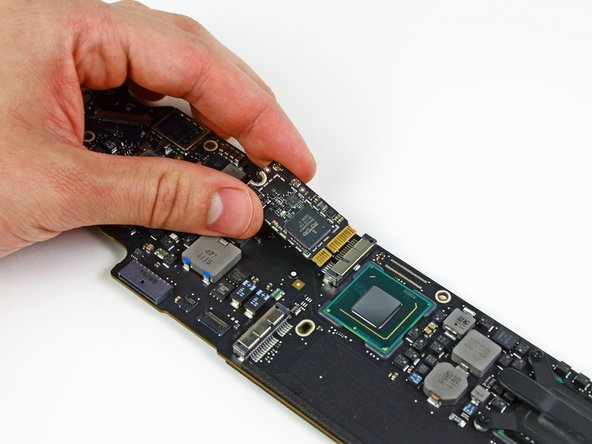
    • Remove the single 2.9 mm T5 Torx screw securing the AirPort/Bluetooth card to the logic board.

  32. MacBook Air 13" Mid 2011 Logic Board Replacement: step 32, image 1 of 2 MacBook Air 13" Mid 2011 Logic Board Replacement: step 32, image 2 of 2
    • Slightly lift the free end of the AirPort/Bluetooth board and pull it out of its socket on the logic board.

    • Remove the AirPort/Bluetooth board from the logic board.

  33. MacBook Air 13" Mid 2011 Logic Board Replacement: step 33, image 1 of 1
    • Remove the four 2.5 mm T5 Torx screws securing the heat sink to the logic board.

  34. MacBook Air 13" Mid 2011 Logic Board Replacement: step 34, image 1 of 1
    • If the heat sink seems to be stuck to the logic board after removing all four screws, use a spudger to carefully separate the heat sink from the faces of the CPU and GPU.

    • Remove the heat sink from the logic board.

    • When reinstalling the heat sink, be sure to apply a new layer of thermal paste. If you have never applied thermal paste before, we have a guide that makes it easy.

  35. MacBook Air 13" Mid 2011 Logic Board Replacement: step 35, image 1 of 2 MacBook Air 13" Mid 2011 Logic Board Replacement: step 35, image 2 of 2
    • Logic board remains.

    • When reassembling your logic board, be sure the rubber gasket is installed correctly. The nub on the gasket should mate with the hole cut into the logic board near the heat sink fins.

    • The rubber gasket should attach to the end of the heat sink as seen in the second picture.

Finish Line

84 other people completed this guide.

23 Comments

This does not show the battery removal in the early steps, but it is shown as removed in later steps.

Jason - Reply

Thanks for pointing that out! Missing steps have been added :)

Andrew Optimus Goldheart -

Thanks i fixed my MacBook Air (11 inch) with this tutorial.

My MBA became very slow after a water spill over the keyboard.

Although Hardware check said everything was fine, i disabled the MB and found a spot with corrosion, after removing the corrosion and assembling it was on speed again. the water spill was some months ago so it had some time to corrode and show were a clean was needed :-)

Wat I real appreciatie is the accurate way of description of the connector disassembly :-)

Gert Jan Bollen - Reply

Would it be possible to upgrade this machine to hold a newer logic board?

Get That Geek - Reply

No. There are no compatible logic boards that I am aware of.

Talon -

Add Comment

View Statistics:

Past 24 Hours: 7

Past 7 Days: 23

Past 30 Days: 144

All Time: 85,778