
Lenovo Yoga Tab 3 10 Motherboard Replacement

What you need

  1. Lenovo Yoga Tab 3  10 Motherboard Replacement, Back Cover: step 1, image 1 of 1
    • Open the built-in kickstand.

  2. Lenovo Yoga Tab 3  10 Motherboard Replacement: step 2, image 1 of 3 Lenovo Yoga Tab 3  10 Motherboard Replacement: step 2, image 2 of 3 Lenovo Yoga Tab 3  10 Motherboard Replacement: step 2, image 3 of 3
    • Remove the sticker located directly under the the built-in kickstand to reveal two 0.75 mm screws.

    • Remove the microSD card slot cover. Remove any microSD card (if inserted).

    • Using a Phillips head screwdriver, remove the three 0.75 mm screws.

  3. Lenovo Yoga Tab 3  10 Motherboard Replacement: step 3, image 1 of 3 Lenovo Yoga Tab 3  10 Motherboard Replacement: step 3, image 2 of 3 Lenovo Yoga Tab 3  10 Motherboard Replacement: step 3, image 3 of 3
    • Orient the device so the screen is facing you.

    • Carefully insert the spudger along the seam between the screen and back cover and gently separate the back cover from the device frame.

    • Continue to detach the backplate from the frame by moving the spudger around the perimeter.

    • Some force will be required to detach the small plastic braces securing the backplate to the device.

  4. Lenovo Yoga Tab 3  10 Motherboard Replacement, Motherboard: step 4, image 1 of 3 Lenovo Yoga Tab 3  10 Motherboard Replacement, Motherboard: step 4, image 2 of 3 Lenovo Yoga Tab 3  10 Motherboard Replacement, Motherboard: step 4, image 3 of 3
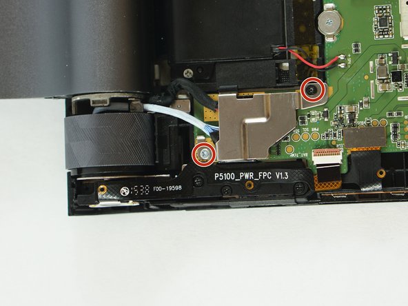
    • Locate the screws in the motherboard the wire cover assembly and the speakers.

    • Use the J000 screwdriver to remove the screws on the motherboard, the wire cover, and the two speakers.

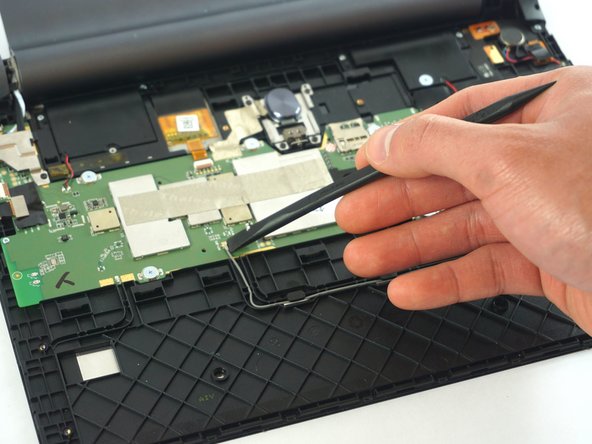
    • Disconnect the wifi connector on the motherboard.

  5. Lenovo Yoga Tab 3  10 Motherboard Replacement: step 5, image 1 of 2 Lenovo Yoga Tab 3  10 Motherboard Replacement: step 5, image 2 of 2
    • Use the spudger to lift the two speakers up from the small adhesive strip.

    • Place the spudger in the upper left corner of the motherboard and lift it to separate it from the adhesive strip under it.

    • Lift away the motherboard.

Conclusion

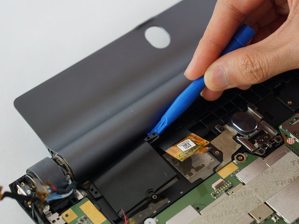
To reassemble your device, follow these instructions in reverse order.

13 other people completed this guide.

Phanudej

Member since: 02/20/17

1,184 Reputation

5 Guides authored

Team

USF Tampa, Team S3-G2, Sullivan Spring 2017 Member of USF Tampa, Team S3-G2, Sullivan Spring 2017

USFT-SULLIVAN-S17S3G2

4 Members

18 Guides authored

One Comment

Dear @phanudej ,

I liked your post. I’d have a remark and a question. I made a mistake during the maintanance; with wich I killed a part of the MOBO. So dear users my advice if you want to connect the LCD connector remove the battery before… I had never this issue but now happened. (the device was switched off)

Could you please take a photo of the powerstage of the LCD (I think it should be that) So between the inductor (100; 10uH coil) and an capacity there is a component I do not know what is it (it smoked away) I assume it is a diode…?! They are in the white rectangle near the LCD connector

Thanks in advance

Best regards

@harrincourt

Jozsef Szlatki - Reply

Add Comment

View Statistics:

Past 24 Hours: 0

Past 7 Days: 6

Past 30 Days: 46

All Time: 9,153