Introduction
One of my LIFX BR30 smart lightbulbs lost the ability to show white light, it always seems to have a blue hue to it. Resetting the software had no effect and the rest of our LIFX bulbs work fine. The bulb is now 5 years old and beyond its 2-year warranty.
After completing Step 1 of the Disassembly Guide, access the white PCB and observe the condition of two resistors that may have cracked solder joints. This guide shows you how to repair those two cracked resistors and return the light to normal function.
What you need
-
-
The diffuser is held onto the bulb's base by four snap-lock plastic tabs, which also have a dab of silicone adhesive on them to prevent the diffuser from rattling.
-
The tabs are just to the right of the small Phillips-head screws you can see in the small space between the diffuser and base.
-
Insert a strong chisel or similar prying tool to bend the plastic tabs. You'll need to bend at least two at once, and then insert something to hold open the one side while you work on the other.
-
After removing the diffuser, remove the rubber white silicone gasket (photos two and three) and set aside.
-
-
-
Removing the diffuser exposes the LED PCB. The edge of the WiFi board can also be seen with the antenna protruding.
-
Note the silicone adhesive on the tabs. You probably don't need to replace this with fresh adhesive, but if you do, make sure it's rated for high temperatures.
-
On the LED PCB, you can see the white and colored LEDs. The PCB is a thermally-conductive aluminum material.
-
Around the edge of the bulb's case there is a plastic retaining ring attached by four Phillips-head screws. It's not necessary to remove this for further disassembly.
-
The LED PCB has a pin header that connects down into the WiFi board. A thermal adhesive pad holds the PCB to the metal bulb case. You can gently pry around the edge of the PCB until the adhesive releases, and the connector separates.
-
On my bulb, the PCB was not fully-seated on the thermal pad, potentially causing heat-related intermittent faults.
-
-
-
The gray material that is solidified around the PCB tears away quite easily, but I stopped here as my light still half-works and I didn't want to risk damaging it further. When we procure more courage, I'll return here to discuss how we removed the gray material that coats the board and steel sidewalls of the PCB's cage.
-
-
-
-
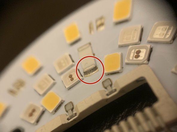
On my BR30, there are two resistors that seem to fail, see red-circled resistors in photo.
-
Use a 10x loupe to look closely at the red-circled resistors, the ends nearest to the center of the PCB may have cracks as shown in Step 2 and Step 3 closeup photos.
-
-
-
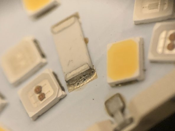
Use a 10x loupe and look at the top resistor and its side nearest to the PCB's center.
-
As shown in the 10x loupe photos on the left, the top resistor on my BR30 had a crack running along the solder joint.
-
-
-
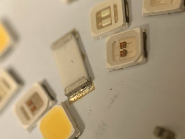
Use a 10x loupe and look at the top resistor and its side nearest to the PCB's center.
-
As shown in the 10x loupe photos on the left, the bottom resistor on my BR30 had a crack running along the solder joint.
-
-
-
Apply flux to the cracked area.
-
Heat your soldering iron to 340 degrees C.
-
Dab solder to the end of your soldering iron, preferably connected to a flat blade.
-
Rub back and forth along solder joint and through flux.
-
Clean with alcohol and inspect your work.
-
-
-
With any luck, your repaired solder joint will look like the repaired solder joints to the left.
-
Note, I'm not good at soldering and I could go over these again to try and remove some of the excess solder.
-
Make sure residual flux is removed with a q-tip soaked in >90% isopropyl alcohol.
-


To reassemble your device, follow the disassembly instructions for the BR30 in reverse order.
To reassemble your device, follow the disassembly instructions for the BR30 in reverse order.
