
Insignia Flex 8 NS-P16AT08 Screen Replacement

What you need

  1. Insignia Flex 8 NS-P16AT08 Screen Replacement, Back Casing: step 1, image 1 of 3 Insignia Flex 8 NS-P16AT08 Screen Replacement, Back Casing: step 1, image 2 of 3 Insignia Flex 8 NS-P16AT08 Screen Replacement, Back Casing: step 1, image 3 of 3
    • Make sure device is powered off.

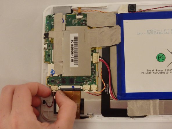
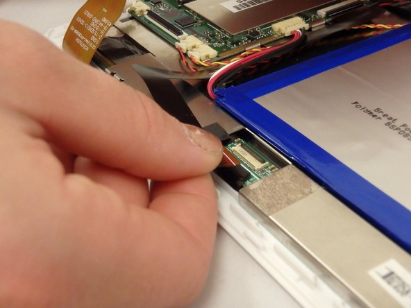
    • Wedge the plastic opening tool anywhere in the seam between the back casing and screen.

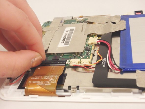
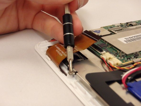
    • Slide the plastic opening tool along the sides and corners of the seam of the device while it separates from the screen.

    • You will hear the popping sound of the plastic connections separating from the device.

  2. Insignia Flex 8 NS-P16AT08 Screen Replacement: step 2, image 1 of 1
    • Lift the back casing away from the screen.

    • Set casing aside.

  3. Insignia Flex 8 NS-P16AT08 Screen Replacement, Screen: step 3, image 1 of 2 Insignia Flex 8 NS-P16AT08 Screen Replacement, Screen: step 3, image 2 of 2
    • Pull gently on the cable that connects the microphone to the motherboard.

    • The microphone will stay attached to device and separated from motherboard.

  4. Insignia Flex 8 NS-P16AT08 Screen Replacement: step 4, image 1 of 2 Insignia Flex 8 NS-P16AT08 Screen Replacement: step 4, image 2 of 2
    • Flip up the black flap of the connector ribbon that connects the screen to the motherboard.

    • Connector ribbon will stay attached to the device and separted from the motherboard.

    • If the black flap of connector will not lift by using your finger, then use the nylon spudger.

  5. Insignia Flex 8 NS-P16AT08 Screen Replacement: step 5, image 1 of 1
    • Gently pull the connector ribbon by hand from the connector until it separates from connector.

  6. Insignia Flex 8 NS-P16AT08 Screen Replacement: step 6, image 1 of 2 Insignia Flex 8 NS-P16AT08 Screen Replacement: step 6, image 2 of 2
    • Flip up the black flap of the connector ribbon that connects the buttons to the motherboard.

    • The connector ribbon will stay attached to the device and separted from the motherboard.

    • If the black flap of the connector will not lift by using your finger, then use the nylon spudger.

  7. Insignia Flex 8 NS-P16AT08 Screen Replacement: step 7, image 1 of 1
    • Gently pull the connector ribbon by hand from the connector until it separates from the connector.

  8. Insignia Flex 8 NS-P16AT08 Screen Replacement: step 8, image 1 of 2 Insignia Flex 8 NS-P16AT08 Screen Replacement: step 8, image 2 of 2
    • Gently pry the cameras from device using metal spudger tool.

    • Always try using a plastic opening tool or nylon spudger first. Metal spudgers are great for serious prying power but can damage your device if used incorrectly.

    • The cameras and connector ribbon will stay attached to motherboard.

  9. Insignia Flex 8 NS-P16AT08 Screen Replacement: step 9, image 1 of 1
    • Remove the tape that is covering the screen motherboard connector ribbon.

    • The screen connection will now be exposed.

  10. Insignia Flex 8 NS-P16AT08 Screen Replacement: step 10, image 1 of 2 Insignia Flex 8 NS-P16AT08 Screen Replacement: step 10, image 2 of 2
    • Flip up the black flap of the connector that connects the screen to the motherboard.

    • If the black flap of connector will not lift by using your finger, then use the nylon spudger.

    • Gently pull the connector ribbon by hand from the connector until it separates from the connector.

    • The connector ribbon will remain attached to the motherboard and separated from the screen.

  11. Insignia Flex 8 NS-P16AT08 Screen Replacement: step 11, image 1 of 2 Insignia Flex 8 NS-P16AT08 Screen Replacement: step 11, image 2 of 2
    • Using a PH00 screwdriver, remove the (7) seven silver screws that connect the metal plate to the device.

    • Using a PH00 screwdriver, remove the (3) three black screws that connect the motherboard to the device.

  12. Insignia Flex 8 NS-P16AT08 Screen Replacement: step 12, image 1 of 1
    • Gently lift the metal plate that is attached to the motherboard and battery and set aside.

    • Do not force the metal plate to separate from the screen!

    • If the metal plate does not separate from device freely, then you have not disconnected a connector ribbon or you have not removed all the screws. Repeat step 10.

    • Screen will now be exposed.

Conclusion

To reassemble your device, follow these instructions in reverse order.

One Comment

Where to buy it the display?

krnes1979 - Reply

Add Comment

View Statistics:

Past 24 Hours: 0

Past 7 Days: 0

Past 30 Days: 3

All Time: 852