Introduction
Over time, the laser toner leaks into the scanning element and can interfere with the printer's ability to produce consistent color. To repair this, we first must disassemble the printer to reach the scanning element, and then clean the optics so the printer produces color as it was meant to.
The first time I did this repair it was with guidance from the pdf attached to the first reply in this thread
What you need
-
-
First, let's establish what part of the printer is what so that we can communicate clearly throughout the guide. The red square is the front and the orange square is the top. After those, we have left (yellow), and right (green). The back is opposite the front and the bottom is opposite the top.
-
-
-
Open the front door and remove the toner cartridges.
-
Set the cartridges aside for later. To keep them clean, place them in a bag or closed box.
-
-
-
Place the printer so that the right side is on the ground.
-
Remove the paper tray from the bottom of the printer.
-
-
-
Rotate the device so it rests on its back.
-
Unscrew and remove the two Phillips M3 screws as indicated from the right side covers.
-
-
-
-
Release tabs on the right base cover and right cover.
-
Some of these tabs are inside the printer, so you will need to open the door and look along the right side.
-
-
-
Place the device right side up once again.
-
Remove the nine indicated Phillips M3 screws from the back plate.
-
-
-
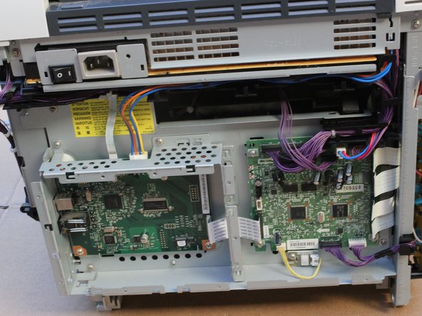
Remove the ribbon cable by pulling directly along the cable.
-
Remove the white connector by pressing down on the tab and pulling out.
-
Pull the purple wire connectors directly out. You do not need to mark which cable goes where, as they are all unique sizes.
-
Remove the white connector by pressing down on the tab and pulling out.
-
-
-
Remove the four ribbon cables gently from the right edge of the circuit board assembly.
-
Remove the final two wires by pulling them straight out.
-
-
-
Unwind the cables from the black harness on the top and right edges of the circuit board assembly.
-
-
-
Depress the indicated tabs and remove the corner wiring harness from the circuit board assembly.
-
-
-
Tilt the printer forward and remove the Phillips screw with a lock-washer from the bottom area of the printer.
-
-
-
Set the printer back down and remove two more Phillips screws with integrated lock-washers, which releases the optical sub-assembly.
-
Remove the optical sub-assembly, this is what you need to repair.
-
-
-
Place the optical sub-assembly with the side that was facing you down.
-
Remove the indicated black screw.
-
Unhook and save the indicated spring.
-
Remove the top plate from the optical sub-assembly.
-
-
-
Using a clean cotton swab or lens brush, GENTLY clean the visible sides of every clear or reflective surface you can find.
-


Team

Cal Poly, Team 10-55, Amido Spring 2014 Member of Cal Poly, Team 10-55, Amido Spring 2014
CPSU-AMIDO-S14S10G55
4 Members
31 Guides authored