Introduction
Since B & W did not respond to my repair request, I decided to open the device myself to repair it.
For me it was just a blown fuse.
(original description in German)
Da B&W nicht auf meine Reparaturanfrage reagierte, habe ich mich entschlossen, dass Gerät selber zu öffnen bzw zu reparieren.
Bei mir war es nur eine defekte Sicherung.
What you need
-
-
Put the unit on its side and then remove the rubber plate from the bottom.
-
then unscrew the four screws (tamper-resistant Torx, but a small screwdriver is enough here).
-
-
-
Carefully remove the ribbon (press the clamp still in front) and lay the docking arm to one side.
-
-
-
-
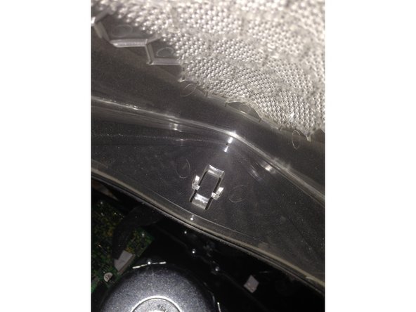
Use a flat plastic tool or a blunt knife in the slot between the chrome bar and speaker cover to push the grille outward, while at the same time pressing the plastic fastener on the back side at the edge. USE CAUTION, the clips can break easily. Then slide the cover slowly to the side.
-
-
-
Remove the 8 philips screws from the front of the unit.
-
The remove the 2 smaller philips screws from the rear of the unit behind the tweeters.
-
-
-
Carefully pull the housing towards you to split the unit apart.
-
Loosen and remove the 3 cables (shown with the RED arrows in the picture)
-
Remove the screws from the power supply (4 pieces shown with the GREEN arrows) and remove the power supply.
-
Remove the screws holding the heat-conducting sheet (5 pieces shown with the YELLOW arrow).
-
solder the new 250V T1,6A fuse to the board
-