Introduction
Every fixer should know their way around a multimeter, which has just north of a zillion uses for testing electronic components and circuits. Follow along to master the three most basic functions of a multimeter.
To learn how to use your multimeter to make advanced measurements such as current and capacitance, check out this guide.
What you need
-
-
A continuity test tells us whether two things are electrically connected: if something is continuous, an electric current can flow freely from one end to the other.
-
If there's no continuity, it means there is a break somewhere in the circuit. This could indicate anything from a blown fuse or bad solder joint to an incorrectly wired circuit.
-
-
-
Plug the black probe into the COM port on your multimeter.
-
Plug the red probe into the port labeled with a V symbol (in this case, the right port).
Why do we need to make sure that no current is running through the circuit?
When there is another parallel branch with 24VDC power and 4-20mA output, the value of the resistance measured comes as zero. Whats the reason?
The way that a meter measures resistance is by sending a small current across the probes and then measuring the resulting voltage. So, another current will disturb your digital multimeter's (DMM) reading.
nicO -
-
-
-
Switch on your multimeter, and set the dial to continuity mode (indicated by an icon that looks like a sound wave).
I want to search the resistance of gold and see if I have some
What does a sound wave look like?
Gold is highly conductive near zero resistance which is why they use it in conducters. Use "specific gravity" type tests or "mass spectromatry" type tests for elements.
Sound looks like sine waves with various amplitudes and cycles per unit of time.
-
-
-
-
Turn the dial to the resistance mode.
-
If your multimeter has manual ranging, set the resistance to the lowest setting.
-
-
-
In this mode, the multimeter sends a little current through one probe, and measures what (if anything) is received by the other probe.
-
If the probes are connected—either by a continuous circuit, or by touching each other directly—the test current flows through. The screen displays a value of zero (or near zero—in this case, 0.8). Very low resistance is another way of saying that we have continuity.
-
If no current is detected, it means there's no continuity. The screen will display 1 or OL (open loop).
It means you have current flowing which would indicate a good path or circuit. Also means you have a power supply connected which I think was mentioned earlier in the article to disconnect all power supplied, as in a.c., d.c. Especially in a vehicle as running tests on computer module circuits with the vehicle battery connected can damage a computer module circuit..
I'm very pleased to have discovered these directions. Interestingly, I tried the two probes on different sections of a screwdriver – resistance showed very high. Is that possibly because of chrome coating on the screwdriver?
May not be a chrome coating at all even if it looks like it. The screw drivers "resistence" is the result of what alloys are used in the shank of the screw driver ... ie ... tin, zinc, carbon, etc.
-
-
-
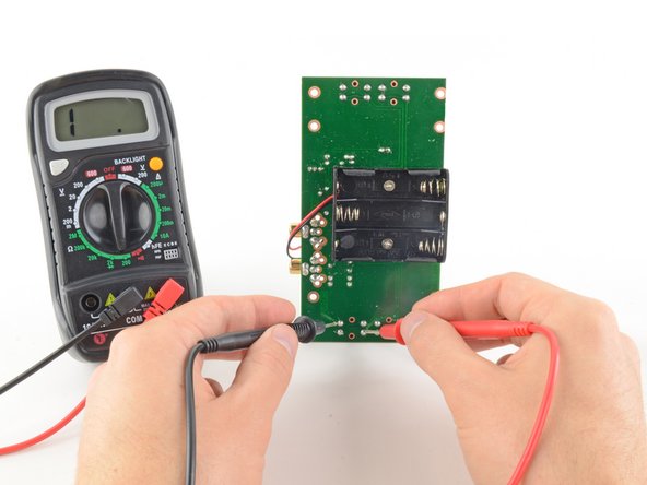
To complete your continuity test, place one probe at each end of the circuit or component you want to test.
-
As before, if your circuit is continuous, the screen displays a value of zero (or near zero).
-
If the screen displays 1 or OL (open loop), there's no continuity—that is, there's no path for electric current to flow from one probe to the other.
What does it mean when I first get 1 then the meter jumps to all kinds of numbers and there is no beeping?
Most likely you have bad contact with whatever you are measuring.
-
-
-
Plug the black probe into the COM port on your multimeter.
-
Plug the red probe into the port labeled with a V symbol (in this case, the right port).
-
-
-
Switch on your multimeter, and set the dial to DC voltage mode (indicated by a V with a straight line, or the symbol ⎓).
-
Each setting on the dial lists the maximum voltage it can measure. So for example, if you expect to measure more than 2 volts but less than 20, use the 20 volt setting.
-
If you're not sure, start with the highest setting.
-
-
-
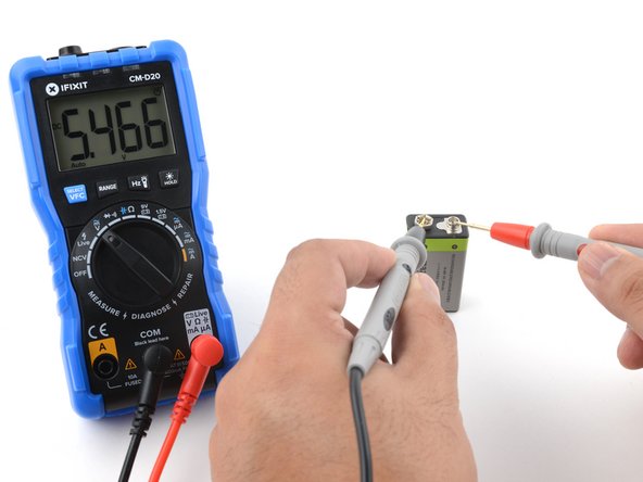
Place the red probe on the positive terminal, and the black probe on the negative terminal. The multimeter will display the measured voltage.
-
Skip the next step, which describes how to measure voltage using manual ranging multimeters.
-
-
-
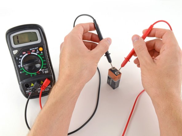
Place the red probe on the positive terminal, and the black probe on the negative terminal.
-
If your range was set too high, you may not get a very precise reading. Here the multimeter reads 9 volts. That's fine, but we can turn the dial to a lower range to get a more precise.
-
If you set the range too low, the multimeter simply reads 1 or OL, indicating that it is overloaded or out of range. This won't hurt the multimeter, but we need to set the dial to a higher range.
-
-
-
To begin, make sure no current is running through the circuit or component you want to measure. Switch it off, unplug it from the wall, and remove any batteries.
-
Plug the black probe into the COM port on your multimeter.
-
Plug the red probe into the port labeled with an Ω symbol (in this case, the right port).
Be careful when testing ohms on the circuit board, the best test is to remove the part so you are only testing the part not the circuit around the part. Transistors, resistors, caps need to be removed or at best one leg of the part. One time I had a burn open resistor, then I tested the resistor with my Ohms test I got some resistor reading. This was caused by back feed in the circuit.
-
-
-
Place one probe at each end of the circuit or component you want to measure.
-
If your multimeter is manual ranging:
-
If your multimeter reads close to zero, the range is set too high for a good measurement. Turn the dial to a lower resistance range.
-
If you set the range too low, the multimeter simply reads 1 or OL, indicating that it is overloaded or out of range. This won't hurt the multimeter, but we need to set the dial to a higher range.
-


Cancel: I did not complete this guide.
1004 other people completed this guide.


132 Comments
EASy and helpful indeed
Iwant to know hw to test caperstas
Thank you. Very easy and good training
Very helpful for beginners, thanks for these clear instructions!
great article. thanks
thank you !!! for this info!!!
Thanks a lot this is very clear and helpful!
Thanks Jeff. I just purchased a cheap mm. All instructions were in Chinese. Your help made sense of it all, so easy.
Iwant to knw hw to test power suply
Brilliant thank you
It truly does.
so nice Bro...Thanks a lot...
Thanks a lot
Love the resources on the Pro site.
Very good instructions
Nice guide.pl add some additional examples to have better understanding for beginners.Thank you
Nice guide. Pl add some additional practical examples. Thank you.
I'm doing exactly this and mine won't read any voltages, but it will read resistance. I've tested it with multiple batteries that I know work, but I only get a read of 0. What might be the problem?
Thank you, Haven't used one of these is ages; this was a great refresher!
thanks for a very easy tutorial, it is very helpful!
The basics. Soooo important. Well done, short and concise.
Most helpful thank you!
Had multimeter for a couple years, never knew how to make it beep!
Thank you for these great instructions. The instructions that came with the multimeter were not helpful for a beginner, and these really helped us diagnose our problem.
Thank you for the great instructions. My question and the reason for my looking online for info on using a multimeter was to find out what the various resistance readings mean on a digital tester. I am checking out a defrosting element in my refrigerator and got a reading of 12 or 15 ohms. The information I was reading said a 15-100 ohms meant the element was OK, another book said if medium resistance was found it was OK.
By going online I was looking for the answer as to what is low, medium and/or high resistance ranges are.
I did enjoy your instructions, they were easy to understand.
I have used a meter for a long time. Never had instructions so clear and easy to follow. Thank you very much.
The pictures are also very clear and helpful.
Beautifully put. I truly appreciate the lesson. I've learned something of impirtance. Thank you.
it really useful for begginer
Thanks you for the lesson :)
Hi,
das ist wirklich sehr anschaulich aufgebaut und benutzerfreundlich, vielen Dank dafür!
Wer jetzt noch genau wissen möchte wie Multimeter funktionieren und worauf Sie beim Kauf achten sollte der kann gerne noch auf https://multimeter-tester.de schauen und weiter lesen.
Ich wünsche euch noch einen schönen Abend und einen bestmöglichen Start ins neue Jahr.
LG
Thanks you for the lesson :)
Thanks and had help me a lot
Had help me a lot. Many Thanks
Thanks , sometimes need too refresh with the basics.
Very informative! Easy to understand.
Well written.
Simple and easy thanks
I have been searching a tutorial on getting started with trouble shooting an automotive parasitic draw. I have no background in different types of functions of a mmeter such as continuity, voltage, and resistance, your tutorial was a must have. It gave me an understanding of just the basic terminology of the more advanced tutorials. I give it a major thumbs up, excellent tutorial thanks a million !!!!!!
Thank you. This was very helpful to me. Very clear and easy to understand....
Thanks for supportive/useful post
Very Helpful.,thanks
Excellent please give us more of the same, primarily to help with understanding of the subject matter at a basic level.
Excellent and elegantly simple guide.
Thanks you so much for this.For me as a beginner,I didn't find difficulties in reading this but its fruitful one.
thanks a million
It was just awsome.Before your tutorial it just was looked like some alien device to me and now I think it's having very simple working principle. I am now pretty confident to work with it. A very big thanks.
Awesome thanks.. I knew you could use this for a lot of things but not this much.
I have a problem with my multimeter (Mastech MY74), the first thing I did was stupid, haven't read the user manual and tried it on a live socket and now it doesn't want to work. I have changed the fuses (600V, 0,4A and 10A), but it still doesn't work. Does anyone have an idea what else could have went wrong and how to test it?
Best regards
Very useful. I liked the statements like ‘this will not harm the multimeter but will show negative reading ‘. For non science folks like me, these questions crop up often so this guide takes away the anxieties.
Nice article with great illustrations.
Apart from measuring DC voltage, resistance and continuity, they can also measure AC voltage, DC current, transistor and Diode checking, which I learnt from here https://circuitdigest.com/article/how-to...
Following the KISS method of instruction!
Very well done!
marvellous explanation for a layman good luck& thanks
Excellent guide. Very well explained and easy to use.
Dead easy. Very impressed.
Thanks a lot. :) My fear with multimeter is gone now. I am able to measure with confidence.
Jeff, thanks for your step by step multimeter guide. I have also written https://bestmultimeterreviews.org/ similar article in my blog. But, your article is much better than me.
Simple, easy to understand, well presented. Very helpful thanks.
Tanks very much….Its really
Thank you. Very clear and thorough.
Very helpful :) Thank you.
Helpful thanks
Cool keep up the good work and thanks
thanks for a very easy tutorial, it is very helpful! pl add some additional examples to have better understanding for beginners.Thank you
sateesh
Thank u for the precise description,very very useful for beginners.
A MAZUMDER
thanku for guide!!!
I studied multimeter in my 11th grade and since then, haven’t been around these things for a long time! I was glad to go through the above instructions and as my nephew has been studying physics as well, I was able to guide him through some subjects which really gave me a good day and made my nephew happy. Thanks a lot.
Very good explained well. Thank you.
Exceptional directions and explanations for each step. Even an inexperienced user (such as myself) can understand and follow the instructions. So hard to find such detailed instructions for those that “want to be in the know”!! Kudos! You deserve 4+ Stars :)
We thank you for the information
I was always confused about electricity and how to test it but your instructions have given me a better understanding of it. I now have a place to go to for future reference. Thanks.
thanks for the lucid description of the three phases of testing an electronic item; good job!
An excellent guide. Thank you.
Thanks, that's helpful to me
Congrats for showing us the best way use it
Excellent guide Thank you!!!!
Well. .. thank you, this is awesome
thank you very much
Well done. You've explained it in detail and was completely understandable. Tm
Good Content …………..Easy to Learn!
When testing a Tweeter the multimeter reads OL on the resistance scale. What does this mean?
Really helpful
Very simple and easy to understand. Thank you very much for your help, now I can use a multimeter now.
Very informative ; Thank you ?
Thank you so much for making it so simple to follow. Because before I new what I was doing I got the all wires mixed up on my car battery. And I nearly melted my fingers to the wires. So thanks again c foley… craigfol659@gmail.com
Very good explained! Thanks.
easy to understand
Thanks for teaching me
Thanks very helpful
Thanks. Very Helpful
Thank you so much easy and healpful
Thank you! Great how to advice for a beginner!
Thanks for the very detailed guide, good content and quality pictures.
AC is not dangerous, even V's aren't. Everyone must get worried about A's.
Sadly, you didn't include how to measure A (amperage or current), which always causes troubles to measure, to learn and understand.
Hi how can I test a signal transmission through an ffc or fpc cable using a multimeter
That was a really clear and concise tutorial. Thanks.
Just one request. Could you do ones on other capabilities of a DMM, please? For example, measuring ampage, testing doids and LEDs.
Cheers Wal