Introduction
This guide will take you step by step on how to replace the motherboard of your DX-WEGRTR router. There are multiple reasons why you'd want to do this, including electrical damage due to a power surge, or a simple broken electrical component within it such a capacitor. Refer to the troubleshooting page to see other causes of possible motherboard malfunctioning.
What you need
-
-
Remove the two Phillips #00 screws in the bottom of the device securing the casing.
-
Two 7.8 mm Phillips screws
-
-
-
Gently pry the edge of the vessel with a plastic opening tool, the previously used screwdriver, or your hands. Move your tool around all the edges of the router until you get all four of the plastic holders.
-
-
-
-
Use your handy Phillips screwdriver to unscrew the Phillips #00 screw to the lower left side of the motherboard.
-
One 4.4 mm Phillips #00 screw.
-
-
-
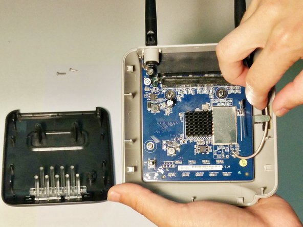
Carefully slide the plastic housing of the antennas (the back cover of the router) up and out of its slot.
-
You may need to move the motherboard at this time in order to giggle the antenna's housing off.
-
-
-
Finally, remove the motherboard from its place making sure to not pull the cable connecting the antennas.
-


To reassemble your device, follow these instructions in reverse order.
To reassemble your device, follow these instructions in reverse order.
Cancel: I did not complete this guide.
One other person completed this guide.

Team

USF Tampa, Team 1-19, Donnelly Fall 2014 Member of USF Tampa, Team 1-19, Donnelly Fall 2014
USFT-DONNELLY-F14S1G19
1 Member
2 Guides authored