Introduction
The Canon PowerShot S100 (as well as other models in this series) is prone to a problem in which a message appears on the screen saying "Lens Error - Will Shut down automatically - Restart camera," and the lens will is stuck in place (either extended or retracted). This error can be caused by a number of different things - a quick search will pop up lots of suggestions, many of which are less involved than the full lens replacement. Try some of those first if you like - if none of them are successful, replacing the entire lens assembly is the next step, and this guide will lead you through it. The replacement part is generally available on eBay for $35-50.
Note that this project involves a number of small screws of different sizes - I strongly recommend using a magnetic project mat with a whiteboard surface to keep track of which screws came from where as you remove them from the camera. Alternatively, place screws on a sheet of paper, label, and stick in place with tape. When removing screws, hold camera over a table or other smooth surface where small screws will be easy to find if you drop them.
Some other cameras are mechanically pretty similar to S100, for example Canon PowerShot S200 (code PC2033). This guide can be applied to those models, too, although there are minor differences in assembly steps, for example: WiFi module and its plastic support piece is easiest to be removed together with the top case; the heat sink sheet needs to be unscrewed from the circuit board in order to access the bottom lens cable; most of the connectors have folding locking levers which must be turned to release/lock the cable. (Note that different models have at least different CCDs, so any lens assemblies themselves are not exchangeable between camera models.)
What you need
-
-
If you are getting the dreaded "lens error" and have exhausted other options, read on.
-
-
-
Before disassembling camera, remove battery.
-
Remove six outer case screws - two each from left end, right end, and bottom.
-
-
-
Lift front case away from camera, being careful not to damage front control ring ribbon cable.
-
Unplug front control ring ribbon cable and set front case aside.
-
Remove lens dust gasket.
-
-
-
Unplug microphone ribbon cable from front of camera. If you need to, insert something pointy into hole in cable and use that to pull cable out of connector.
-
Gently remove microphone assembly (may be slightly stuck to bracket on top case).
-
-
-
Remove screw that secures top case to right end of camera, above media ports.
-
Remove screw securing top case to front of camera above lens (longer than other top case screw).
-
Remove top case from camera.
-
-
-
On front of camera, disconnect ribbon cable for rear control panel, flipping up brown clip (flips away from cable) and pulling cable gently out of connector.
-
Unclip & disconnect ribbon cable for LCD (under rear control panel ribbon).
-
-
-
-
Turn camera over & remove display bracket screw from near top-right corner of display.
-
Remove display bracket.
-
-
-
Unplug small ribbon cable from rear control panel (connects LCD to rear control panel).
-
Remove screws from outside edge of rear control panel (bottom screw is shorter than top one).
-
-
-
Remove rear control panel & display, threading ribbon cables through slot in camera body.
-
-
-
On back of camera are seven screws around opening through which you can see back of CCD & lens assembly. I recommend numbering them with a marker & putting corresponding numbers on your project mat to keep the screws organized as your remove them.
-
Label screw on far left #1 and procede clockwise.
-
-
-
Unplug flash ribbon from top of camera next to GPS antenna.
-
Remove screws 1 & 2 from camera back.
-
Remove flash unit from camera. Handle flash unit carefully, as it contains a capacitor which can shock you (but no need to be super worried - I've done this lots of times and have never been shocked).
-
-
-
Unplug GPS ribbon cable from front of camera.
-
Un-stick & fold up flash cable receiver to reveal screw, then remove screw (top of camera, left of GPS antenna).
-
Remove second screw from other side of GPS antenna (longer than other screw, and may be a darker color).
-
Remove GPS antenna and shield underneath.
-
-
-
Disconnect CCD cable, prying up gently (front of camera next to lens).
-
Unclip & disconnect lens unit ribbon cables (above and below CCD cable).
-
-
-
Remove remaining 5 numbered screws (3-7) from back of camera (numbers 5 & 6 are shorter than all the other numbered screws and different from each other; other numbered screws appear to be the same size, including 1 & 2).
-
-
-
Turn camera over and remove lens assembly. This may take a bit of wiggling. Lift bottom right corner slightly, then pull lens assembly gently right and it will slide out.
-
-
-
Follow steps in reverse order to reassemble. See next steps for reassembly tips.
-
-
-
If your replacement lens assembly does not include a CCD (sensor), you can swap the CCD from the old lens assembly to the new one.
-
Carefully scrape 5 glue dots from edges of CCD on old lens assembly.
-
Remove 3 screws securing CCD to back of lens assembly and remove CCD, noting any tiny brass washers/spacers that may be present where screws were. Remove CCD, being careful not to touch or get dust on sensor surface.
-
Carefully remove rubber infrared filter gasket and infrared filter (small rectangle of bluish glass) from back of old lens assembly & install on back of new lens assembly.
-
Install CCD on back of new lens assembly (may or may not need to use brass washers to get alignment right for correct focus).
-
Note: S100 & S110 CCDs are not interchangeable - ribbon connector for the S100 lens assembly is larger, & does not fit on the S110 board connector.
-
-
-
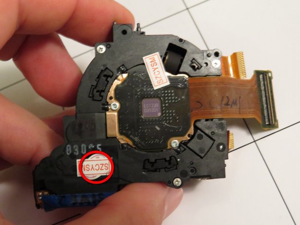
You may need to remove a sticker on the back of the replacement lens assembly to uncover one of the screw holes (screw #7).
-
Rotating the lens assembly slightly counterclockwise as you get it into position can make it easier to get it fully seated.
-
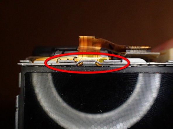
It may be easier to get the ribbon cables for the new lens assembly plugged in BEFORE replacing the 5 screws that hold the lens assembly to the camera body. Lower/smaller one is especially tricky - I have found that it is easiest to get it fully seated with the lens assembly not quite in place.
-
If, after completing reassembly, lens error persists, double check that lower lens unit ribbon cable is fully plugged in (can be hard to get it all the way in). If it is not fully seated it will cause a lens error.
-
-
-
Display slides in from the right, with tabs on left end that hook into metal camera chassis.
-
Lower/right end of lens bracket hooks in first.
-
Upper/left end of lens bracket weaves between projections on metal camera chassis.
-
Rear control panel screws go on the outer edge - easy to accidentally put upper one into hole where display bracket screw goes.
-
-
-
When replacing the top case, remember that the end screw goes on the right end of the camera (the screw hole on the left end is filled by one of the outer case screws). There are two screw holes on the right end - this screw goes in the hole on the left/closer to the rear of the camera (again, the other is for one of the outer case screws).
-
-
-
If all goes well, camera should power on and prompt you to set date/time.
-
If the lens extends and the display turns on but is blank, remove the front case and disconnect display ribbon cable, then reconnect it (under rear control cable - see step 8). This can happen even if it seems like it is fully seated, and reconnecting it will usually fix it.
-