Introduction
For this guide, we are using an older CR-10 Mini that has been updated with the same motherboard as a CR-10S. Start by removing the control box and placing it in a well lit place where you can sit comfortably.
-
-
Turn the power switch to OFF
-
Unplug the power cable
-
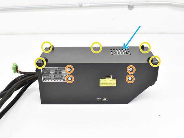
Using an M2 hex, remove the 5 button head screws holding the control box bottom cover on.
-
using an M2.5 hex, remove the 4 button head screws holding the power supply to the control box.
-
Lay the power supply to the side as shown.
-
Remove the grommet from the rear of the control box and pull back a few inches as shown.
-
-
-
With the grommet loose, you can feed harness A through the grommet with the 2 and 3 pin connector going first.
-
Leave 4-5 inches of the loose pins and reinstall the grommet.
-
-
-
After feeding harness A into the control box, note where everything is connected in case you have remove things like the LCD connections to access the new connection points.
-
Plug in the 3 pin connector to D11 row with the red wire on the V pin. For CR-10S machines, it is the pin closest to the LCD connections.
-
Plug in the 2 pin connector where the original Z end stop was plugged in. This is Z- for CR-10S machines.
-
Zip tie harness A to the original harness group for strain relief.
-
-
-
If you're going to glue the new connections in, do it now.
-
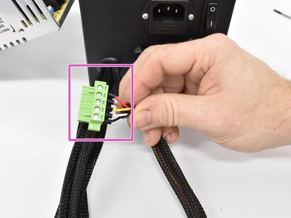
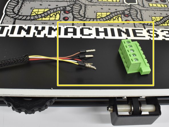
Install the male green phoenix connector onto harness A.
-
Using a flat head screwdriver, loosen the terminals 3-4 turns then insert the wires into the
-
Reinstall the power supply and tighten the screws.
-
Reinstall the bottom cover and tigthen the screws.
-
-
-
-
Reinstall the power supply and tighten the screws.
-
Reinstall the bottom cover and tigthen the screws.
-
The vent holes should be positioned over the power supply.
-
-
-
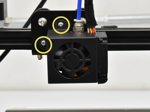
Using an M2 hex, remove the 2 button head screws holding the hot end shroud on.
-
Install the bracket using the provided M3x8 (or 3x10) screws.
-
-
-
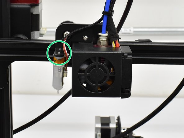
Plug the small end connector into the probe. It will only plug in one way so do not force it.
-
Install the probe as shown with the connection facting the hot end. Use an M2 hex to install the provided M3x6 screws.
-
You can now install the pre-crimped wires into the phoenix connector. Match the color order from the motherboard side.
-
-
-
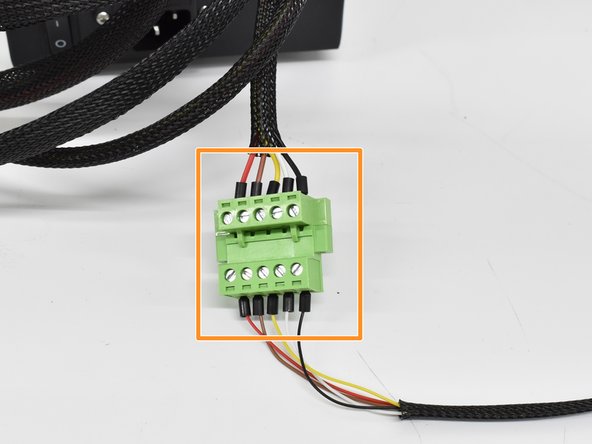
Double check that the colors match from the motherboard side to the probe side and plug the motherboard side into the probe side.
-
Provided zip ties can be used to attach the new harness to the original in the locations shown.
-
Be sure to leave a little slack in the probe harness so it is not pulled on when the X axis moves back and forth.
-
-
-
Please contact us regarding firmware if you have purchased our BL Touch Kit for the CR-10S.
-


Team
