Introduction
This guide shows you how to replace, or alternatively bypass the speed control board on a Bosch gst90be Jigsaw
The techniques involved are probably applicable to other models.
This guide involves working on a mains electrical device, so make sure it is disconnected from the power supply before starting.
Anyone following this guide should be suitably skilled and aware of electrical safety.
They take this guide as advice at their own risk.
The author takes no responsibility for damage of injury resulting from following the
information in this guide.
What you need
-
Step 1 Diagnosis
Careful: steps 1-6 are sourced from a guide that's marked as in-progress.
-
This is the Bosch gst90be, a hand held Jigsaw from the Bosch Pro range.
-
This guide will show you how to disassemble it to make repairs.
-
-
-
Undo and remove 5mm Hex screw and square washer from Shoe, and remove shoe.
-
-
-
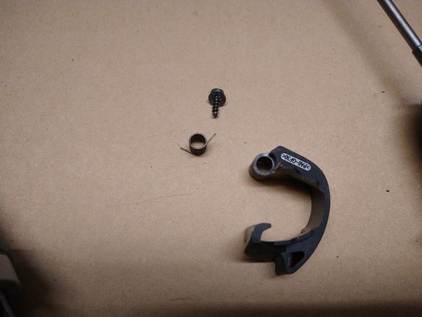
Remove 1 T20 Torx screw and washer from blade lever, then remove blade lever and spring.
-
-
-
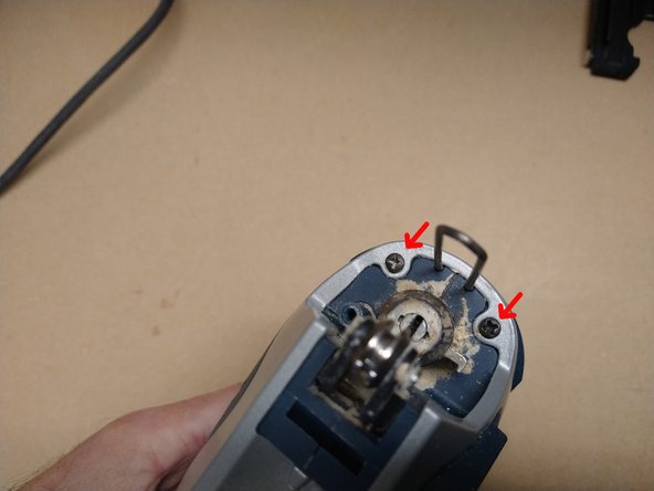
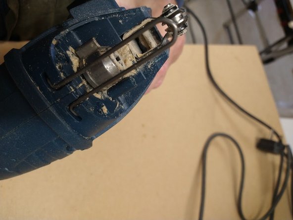
Remove 2 Posidriv screws from front cover, then slide off front cover and remove wire blade guard, which rests in a recess behind the metal cover.
-
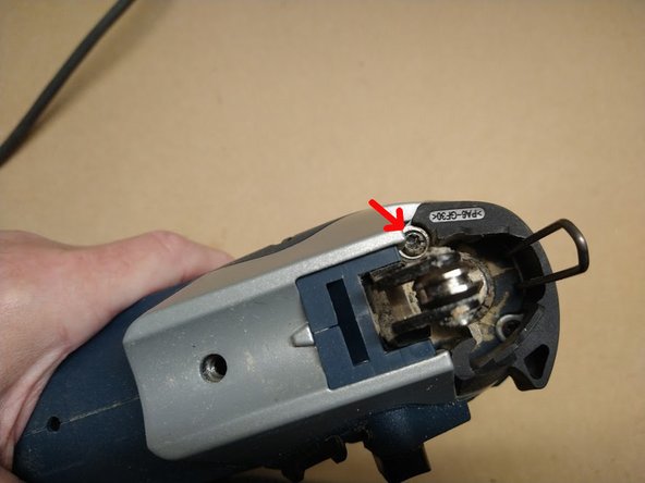
Remove one Torx T20 screw
-
-
-
-
Remove eight T20 Torx screws from the body of the saw. (The ninth screw was under the silver metal cover).
-
-
-
You can now separate the two halves of the saw, which allows you to access all of the components
-
To reassemble the saw, follow the instructions in this guide in reverse order.
-
-
-
There are 4 main types of electrical problem with a Power tool, Cable, Motor, Switch or Speed control.
-
The cable and switch can be easily checked out with a meter, as can the motor.
-
If all of these seem OK, then the speed control PCB may have failed. When the board fails, the drill just does not work at all.
-
Before replacing the board, it is worth blowing some compressed air through the speed Knob, as these can get full of dust and that will stop the saw working.
-
-
-
If you have disassembled the saw using the previous instructions, you can now access all of the components.
-
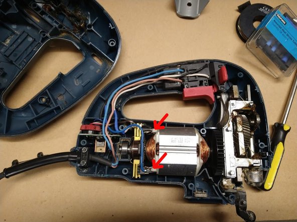
The Control board is at the rear. as shown in the main image. It can slide out now that the case is separated.
-
It is connected to the motor by two wires with copper push-in connectors, a blue one at the front and a white one at the other side, which is under the motor
-
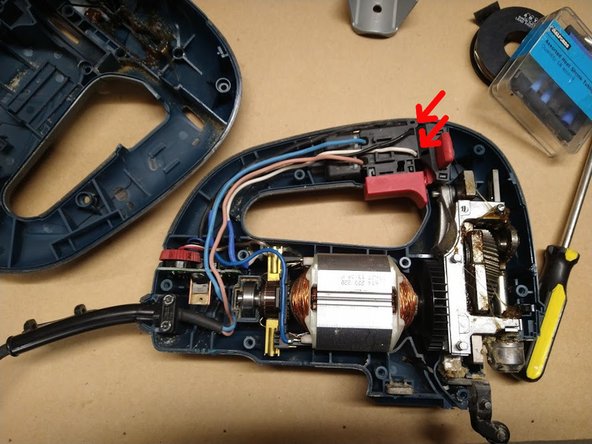
There are two longer wires leading to push-in connectors on the switch, a black one and a white one. There is also a multi-pin connector for the speed control cable.
-
-
-
If , like me, you never use the speed control on the Jigsaw, you can remove it permanently, and bypass it.
-
To do so, you will need to cut the wires between the switch and the PCB, and the PCB and the motor.
-
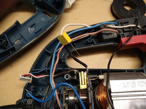
Then join the white wires together, and the black and blue wires together. The multi-pin connector is for the variable speed trigger and is not required.
-
I did this by soldering them together and covering the joints in Heat-shrink tubing.
-
It is recommended to add an X2 0.1μF 310V capacitor between the white and black wires to prevent electrical noise and excessive sparking from the motor brushes, which would shorten the life of the motor, I did this by soldering one leg of the capacitor to the joint between the white cables and one to the joint between the blue and black wires.
-
Take care that the wires are routed correctly through the notches in the case frame, so they will not be compressed when you reassemble the saw
-
-
-
This is the type of capacitor I used, available very cheaply on Ebay
-


To reassemble your device, follow the instructions from the first guide in reverse order.
To reassemble your device, follow the instructions from the first guide in reverse order.
Cancel: I did not complete this guide.
One other person completed this guide.
2 Comments
Bravo Mr. Maxwell. More of your lessons will be appreciated
The same values would be fine.
The 310V value is just a maximum tolerance, that capacitor would be fine for 110v.