
ASUS MeMO Pad 7 (ME572C) Motherboard Replacement

What you need

  1. ASUS MeMO Pad 7 (ME572C) Motherboard Replacement, Rear Panel: step 1, image 1 of 2 ASUS MeMO Pad 7 (ME572C) Motherboard Replacement, Rear Panel: step 1, image 2 of 2
    • Make sure your device is turned off. Then with a plastic opening tool, carefully remove the back panel by carefully working your way around the perimeter.

    • The panel will be glued on and requires pressure to open.

  2. ASUS MeMO Pad 7 (ME572C) Motherboard Replacement: step 2, image 1 of 3 ASUS MeMO Pad 7 (ME572C) Motherboard Replacement: step 2, image 2 of 3 ASUS MeMO Pad 7 (ME572C) Motherboard Replacement: step 2, image 3 of 3
    • After removing the rear panel, use a plastic openning tool to remove the frame of the tablet.

    • Start in the middle of the top side and insert a plastic opening tool between the screen and the frame.

    • Carefully run the plastic opening tool along all the edges of the tablet.

  3. ASUS MeMO Pad 7 (ME572C) Motherboard Replacement: step 3, image 1 of 1
    • When you take the rear panel and the frame out, place the rear panel and the frame away from the device.

    You do not need to separately remove the back and the frame. You can do it in 1 step if you start around the screen and remove the frame and back together.

    Visegradi Istvan - Reply

    Where can I find rear panel please help?

    Simeon Tembo - Reply

    Exact, on peut déposer le volet arrière en 1 seul fois. Commencer sans outil, juste avec les mains en forçant légèrement sur un angle inférieur (droit ou gauche peut importe) afin de déboîter un premier clips-plastic. Puis avec un outil fin en plastique (pas de métal de préférence !) faire le tour de l’écran afin de déboîter tous les clips-plastic. Merci pour ce post.

    Loïc MALECOT - Reply

    To keep the frame notches intact, pry the frame first sideways, then to the back, lifting the outside notches of the frame over the inside notches of the device.

    My rear panel seems welded together with the frame, so came off as a whole. I noticed 8 inside/device notches of the total 4x6 notches broke in the process.

    Before disassemble, I noticed in the middle on the longer side, next to the power button, already a gap, through which I saw the copper shining of the sidekeys part. Maybe because of temperature expansion or strain of the elastic corner clips of the sleeve I used.

    Eduard - Reply

    Correction: “To keep the frame notches .. device.” = “Notches on the plastic motherboardchassis are snapped over notches of the outside frame locking both together. To keep the chassis notches intact, .. chassis.“

    Eduard -

  4. ASUS MeMO Pad 7 (ME572C) Motherboard Replacement, Battery: step 4, image 1 of 3 ASUS MeMO Pad 7 (ME572C) Motherboard Replacement, Battery: step 4, image 2 of 3 ASUS MeMO Pad 7 (ME572C) Motherboard Replacement, Battery: step 4, image 3 of 3
    • Disconnect the ZIF connectors to release the data cables holding the battery in. Use tweezers to do this.

    • You can also use your hand to remove ZIF connectors.

    • ZIF connectors are delicate so be careful when you are removing them.

  5. ASUS MeMO Pad 7 (ME572C) Motherboard Replacement: step 5, image 1 of 1
    • Find the place where the battery connector is. Disconnect the battery connectors by carefully pulling up on them using a spudger or plastic opening tool.

  6. ASUS MeMO Pad 7 (ME572C) Motherboard Replacement: step 6, image 1 of 3 ASUS MeMO Pad 7 (ME572C) Motherboard Replacement: step 6, image 2 of 3 ASUS MeMO Pad 7 (ME572C) Motherboard Replacement: step 6, image 3 of 3
    • Using a plastic opening tool carefully pry the battery loose. The battery is glued to the pad; slight pressure will be needed to remove the battery.

    • The casing of the battery is soft and can easily tear. Tearing can lead to the chemicals in the battery to leak out.

  7. ASUS MeMO Pad 7 (ME572C) Motherboard Replacement, Motherboard: step 7, image 1 of 2 ASUS MeMO Pad 7 (ME572C) Motherboard Replacement, Motherboard: step 7, image 2 of 2
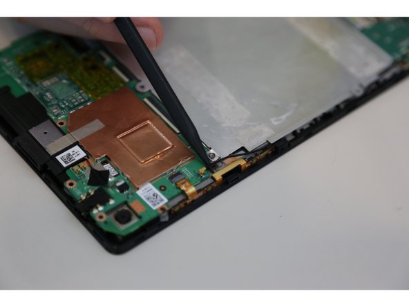
    • After removing the battery from the device, locate the volume connectors on the side of the device.

    • Using tweezers, carefully remove the volume connectors and place it to the side.

  8. ASUS MeMO Pad 7 (ME572C) Motherboard Replacement: step 8, image 1 of 2 ASUS MeMO Pad 7 (ME572C) Motherboard Replacement: step 8, image 2 of 2
    • Locate the GPS antenna. Pry off the GPS antenna cable with a spudger.

  9. ASUS MeMO Pad 7 (ME572C) Motherboard Replacement: step 9, image 1 of 2 ASUS MeMO Pad 7 (ME572C) Motherboard Replacement: step 9, image 2 of 2
    • Locate seven 2mm Phillips #0 screws attaching the motherboard to the pad. Remove the screws with a Phillips #000 screwdriver.

    • Place your screws somewhere you will remember they are at.

    There were eight screws on both of the motherboards i just swapped. The last one would be in the top left of the diagram.

    mesanos - Reply

  10. ASUS MeMO Pad 7 (ME572C) Motherboard Replacement: step 10, image 1 of 1
    • Once all the screws are taken out, you can remove the motherboard. Carefully, take the motherboard out with a plastic opening tool.

Conclusion

To reassemble your device, follow these instructions in reverse order.

3 other people completed this guide.

Tyler Tripp

Member since: 08/26/15

395 Reputation

2 Guides authored

Team

USF Tampa, Team 14-23, Meier Fall 2015 Member of USF Tampa, Team 14-23, Meier Fall 2015

USFT-MEIER-F15S14G23

4 Members

14 Guides authored

3 Comments

hi, i need the power supply board where the usb in. please let me know where i can buy one. Asus MeMO Pad 7 (ME572C)

i think it called pcb

Feroz YF - Reply

Hello, I have a broken Memo Pad that doesn’t power on anymore. The mainboard seems ok though. If I switch the board of the broken asus to another device, will I then be able to boot the system as it was on the old device?

Pen Guin - Reply

Many thanks to this guide. With the instruction I could repair my dead screen. The yellow/orange screen cable was just a little bit out after a 40 cm drop. Just pushing the battery a little bit in the direction of the motherboard was enough to reconnect the screen … I suspect that the weight of the battery pulled the video cable out of the the connector as the video cable is attached to the battery pack with adhesive tape.

Dekerser Dekkers - Reply

Add Comment

View Statistics:

Past 24 Hours: 1

Past 7 Days: 7

Past 30 Days: 14

All Time: 3,945