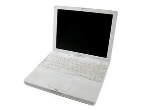
Model M6497 or A1005 / 500, 600, 700, 800, or 900 MHz G3 processor

117 Questions View all

Display black /are there any vital screws?

Block Image

Another day, another disaster. Husband bought this for me to fix for him. (says I hog the Mac..don't know why he thinks that) Advertised as not powering on. Opened the box, pressed the power button and you can hear the hard drive/fans/chime but the LCD is black...no faint images/no cracks etc that I could see. Decided to try the cheap route first and bought the LCD data cable. Opened the iBook up and discovered someone has been here before...some screws missing, Looks like they have done the same repair I planned. Unfortunately there are about 6 stripped screws(+ the missing ones) I planned to just use only the essentials when I put it back together. So the point here is..are any screws a ground etc or vital to the original location?

part 2 of the question..Would you suspect the LCD if it is entirely black? I went for the connection idea because the wires go through the hinge...are these ibooks plagued with graphics card problems and would it give a black screen?

Block Image

Update

This isjust in case anyone ever wants to know which screw goes where...right toward the end of this document is a screw guide and location guide..all free.

Update

ok..have had time to consider options and am going with oldturkeys brilliant suggestion of glue. I didn't think I had enough to make a connection but I don't think size matters here...just need a connection! I have tried soldering what I have, cleaned, fluxed.. solder seems frightened of the board! so have ordered something like this I'll let you know when I get the glue and the "bodge" done. Thanks to all who have tried to help :-)

Update

right have received glue (£5 for 9ml..looks to be enough to glue 300 boards, a real bargain!)..all the way from the USA! waiting for it to cure before I try the start up, but thankyou so much oldturkey for reminding me of this product. Must remember to use brain more often and think outside the box!

Answered! View the answer I have this problem too

Is this a good question?

Score 5
3 Comments

Have you tried an external monitor yet :-) and I do not know anything about Mac's Would you mind to check if this manual is helpful to you and there is some software you could try as well on here not sure if this will work for you. To many Mac manuals that I know nothing about ;-)

by

thanks for the LCD tester. i think you have to have it installed on the computer you are testing,I'm thinking maybe I can boot from this mac and test that LCD. ..always handy to have something like that for my repair disasters.(am not on a winning streak this week..busy night of repairs ahead..managed to pull the power connector off the board! Have 6 stripped screws to drill out, an iMac with half the caps out and a nintendo with a wrecked game slot!)

by

first photo..looking at the bottom right corner of topside motherboard...4 brown parts are where there should be connectors for the power connector. second photo is the underside...I'm interested in the solder "blobs" and what function they may have in relation to my missing connectors.

by

Add a comment

3 Answers

Chosen Solution

I don't think that the solder pads under the board are related to the power switch.

To restore the two solder pads of the power switch you need to apply flux to the two circuits then just a small drop of solder at the end of each circuit. Flux will clean the area where you want to restore the solder pads and using it gives a better chance to obtain solder pads that will stay on board and make a good connection. When your solder pads are restored just solder your two power switch cables to them. Good luck...

Was this answer helpful?

Score 3

4 Comments:

I tried that... The trace is incredibly fine, I thought I'd done a good job with the few mm I had left, but the weight of the wires snapped off almost all remaining trace. Looking at the photos do you think that's enough? Ps.. Solder didn't want to stick to that board with flux, tried that first.

by

ok, so my understanding of this part of the circuit is that only the push power button completes the circuit, which is why people have been able to "jump" start the ibook by putting a screwdriver across whatever is left of the pads. What I'm wondering is where on earth (or in iBook) the + and - pads go..if I know that then I can pop in 2 insulated wires and fix the problem.

by

pollytintop, did you check on the paste/glue that was posted as an answer somewhere. I think it was a Canadian site and was posted as a PCB repair...wish I could remember :-) just an idea instead of using solder

by

honestly there is about 1mm of trace on both pads and at opposite ends! I'm thinking that on the back of the board is a ?resistor with 2 trace lines coming to it and only 1 going out that looks promising. It lines up with where the 2 pads above it would go to. r594... I have made a total *%^$ of this, I scraped back from one pad and found trace but looking at it I think it was something running alongside the original pad, so now I have to fix that! Nothing wants to be soldered! not a happy bunny.

by

Add a comment
Most Helpful Answer

If you thinks it's booting up, hook it up to an external monitor to see if it is a video problem. Meanwhile boot it into Target mode via a firewire cable and run disk utilities on the hard drive. Let us know your results and we can go from there.

Was this answer helpful?

Score 3

6 Comments:

thanks Mayer, i was hoping you'd take a look at my question. Have just resoldered the power connection to the board. Need to reassemble it...what a PITA this thing is! Will take a few hours of swearing..I'll get back to you, but thanks for looking in. Hope you're well? :-)

by

Some machines will not start with screws missing, make sure all the logic board screws are there.

by

blast and double blast! might be alright..we are seriously deficient in that department.

by

right so the soldering job was not so good. The power connection on the motherboard ripped out the pads..found trace, soldered a wire to each trace and then to connector so it'd be better for any time I need to open it up again, thought all was good..picked it up to connect parts back and that blasted trace snapped off! I am not of the opinion that a new logic board is the answer even though every forum says it is. Anyone know where those trace go? any schematics, guru tricks? I am not really such a dunce. That power connector wasnt coming off no matter what I did. Wish I'd cut it now!

by

anyone got a diagram of the power circuit..been out there googling like a mad thing. There is about 0.5mm of trace left..it's as fragile as a hair and did not like being soldered! I'm curious to know whether the 2 solder blobs directly underneath where the original male connector was have any relation to this circuit and if they do whether I could perhaps connect the wires there? Unfortunately until I sort out the power connection issue I can't troubleshoot graphics chip/LCD etc. Not my finest hour. :-(

by

Show 1 more comment

Add a comment

As mentioned before on this thread, use an external monitor.

Here's a very common issue with the iBook (G3&G4). All laptops have a wire bundle leading from the Motherboard to the Display, via the inverter.

Most techs quickly assume one of two things, either the inverer is bad (most common display issue in all model laptops, not sure why). Or, the systemboard, daughterboard or GPU has overheated and failed. Both are fixable in many cases, requiring something as simple as replacing the inverter to something as complex and time consuming as a GPU "Reflow". And, yes, this does apply to Apple Tech's as well.

The true issue, is a bit more illusive, but, quite easily fixed. Provided you can find a "Display Wiring Harness/Bundle" that has NOT come from an already effected unit.

Here in Lies the Rub... The "Display Wiring Harness" is positioned in such a way that after many open's and closes, wriggles it's way loose and becomes pressed against the corner of the hinge (Left Hand Side). This is just enough to cause the wires inside the bundle to rub against one and other causing the outer Teflon coating to become bare in this spot. This is pretty easy to identify, since the outer covering of this harness will be worn or abraded at that pinch point. Although this doesn't always happen, it is often visible. Now hear's the Rub of the Rub, once these wires have made contact, they often cause a "Dead Short" or "Dead Ground" either of these allow the circuit to complete prior to reaching the display/inverter. If this is a "Dead Ground", it most likely has not caused any permanent damage to the board or inverter. However, if this is a "Dead Short" it has completed the circuit without resistance and will most likely result in a fried circuit path on the board or inverter.

So, quick identification of the issue is key in making a proper diagnosis, and not just the immediate "Hands in the Air", "It's dead" conclusion offered by way too many techs.

Quickest solution, with minimal cost, replace the "Display Wiring Bundle/Harness" first (since this will almost always be bad, and if not, you can use it as a diagnositic tool on the next machine). Then the inverter. If the display has not lit up, then you've most likely been left with a bad board. But, at least you have properly diagnosed the issue and are the customers new TECH Hero, or if it's bad news, at least YOU know that you've done this the right way!

Hope this helps, Good Luck

Was this answer helpful?

Score 0
Add a comment

Add your answer

pollytintop will be eternally grateful.
View Statistics:

Past 24 Hours: 0

Past 7 Days: 0

Past 30 Days: 3

All Time: 1,646