
Guides and support for various television (TV) brands and styles.

9048 Questions View all

Hisense 50H5C LED tv has standby light, won't turn on

I opened up and tested the standby voltage at connector but there is no printed voltage. In standby mode I only see .08 volts but when I press the power button I then show 3.8v.

Isn’t there supposed to be 3.3v or 5v while in standby mode with red light on? All the YT videos I watched about checking standby voltage implied this should be the case.

So then what should happen to the standby voltage when the power is turned on?

I have no bulging capacitors and I checked them in circuit with an ESR meter, so far none of them are showing signs of being bad. I understand I may have to remove some components to thoroughly check them.

I checked the bridge rectifier powered off and on and it seems good although the DC voltage is 114v. Is that too low? I saw many videos where it was around 160v.

I checked the LED backlight line from the power supply board when powered on and there is no voltage so it shouldn’t be my LED strips or circuit.

The standby light does blink six times before going off when power button is pushed.

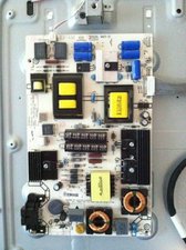
Power board is part number 193287 and mainboard is 194580. I found a kit on Shopjimmy for all three boards including the T con but of course the idea is to become a better troubleshooter and find the bad parts before throwing in the towel.

Block Image

Block Image

Block Image

Answered! View the answer I have this problem too

Is this a good question?

Score 1
1 Comment

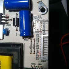
Thanks for your response. Here are the pics of the PS and mainboard as well as the PS connector. Please clarify the startup procedure regarding the standby voltage. Am I supposed to get 3.3v/5v while in standby mode or when I press the power button?

When you say the mainboard turns on the PS how exactly does that work? I disconnected the mainboard to see just what the PS is doing by itself and I still get the two 12v signals as well as the two 16v signals (actually reading 20v as explained above - is this OK?).

My understanding is that the PS would supply a standby voltage to the mainboard which then would allow the functioning of the power button to tell the mainboard to tell the PS to supply voltage to the LED backlight circuits as well as video information and menu function etc.

Do you know anything about what the DC voltage should be on the bridge rectifier? Is this voltage fairly standard in LCD/LED TVs or is it related to screen size?

by

Add a comment

3 Answers

Chosen Solution

Markus

it does sound like a PSU issue due to the standby voltage. Since schematics and manuals are not easily found for your TV, you would need to post some good images of your boards with your question. That way we can see what you see. Use this guide Adding images to an existing question for that. Do not forget to check the main board properly as well. After all, it is that board which turns on the power supply.

Update (09/30/2018)

Markus the voltage on the rectifier sounds about right. There are a few places where the DC voltage gets boosted once the TV turns on but the recitifier sounds normal. The standby voltage seems to be to low. You are right, the power supply provides the standby volaage to the main board. The main board receives signal from the power switch or remote etc. to turn on and "sends" signal to the PSU to turn backlight on etc. Of course, no schematic is available for your model. I wonder if you could try to start it by pulling SW (same as Pwr On on other make?) to ground with a 1K resistor. I do have the schematic for the power supply. See if that will help to further diagnose Schematic Prints

Was this answer helpful?

Score 4

1 Comment:

Wow, that schematic was quite a bonus, thank you. I’m taking off a few components at a time now and testing them so I’ll get back when I find something.

by

Add a comment

I ended up ruining my PS board and had to replace it (even more embarrassing since it’s now looking like I never had a bad board in the TV) but I just went ahead and got the three board set from ShopJimmy to be safe. I did the flashlight test again to verify a signal after I had the same symptoms after replacing all three boards and sure enough there is a signal there. I recall doing this test before but I must have not been thorough, now I'll never know whether I even had any bad boards.

This set doesn’t have a separate LED driver board and I’ve replaced all three boards, besides the fact there is a signal there when using the flashlight means it must be an issue with the LED strips, correct? Or is it possible the new PS board isn’t putting out the voltage for them because when I check for voltage at the LED connector I don’t see any. Shouldn’t there be over 100v DC to power the LEDs at that point where the arrow is pointing in the picture?

My question is:

Does the software run a test while the standby light is blinking after powering on the TV to make sure certain conditions are right before sending the voltage to the LED strips? I don’t want to do all of that extra work to get to the LED strips if I should be checking/changing the PS board again

Thanks.

Was this answer helpful?

Score 1

2 Comments:

Markus failed backlight array would not trigger any firmware hard stop. If you have picture but no backlight and if your PSU and all the other boards are new, it stands to reason that this is a backlight array error.

by

Well after checking the LED voltage with the connector plugged in which I learned from a ShopJimmy video I found I did have adequate voltage so I went deeper and checked all of the LED strips. Four had one bad LED although they still lit up the rest of the lights on each strip so those bad bulbs were shorts. However one strip didn't work and it had two bad emitters but one was an open so it knocked out the whole array. Unfortunately when I removed the screen I noticed a crack that I never heard happen so I didn't want to buy a set of lights. I had some of those xmas light style LEDs around and thought the 2.7v rating would be OK so after soldering those in I powered it up but it only stayed on for a few seconds. I'm assuming their 20ma rating was too low for this circuit but I haven't taken it apart yet. I'm really getting my keester kicked on this one but it's my first so now I can say I've paid some dues. As the pun goes, tough break. Thanks for your input and if I can find a donor set with the same screen I'll post back.

by

Add a comment

I have the same problem with no STBY voltage even though the red light is on when plugged in. The schematic shows STBY as coming in to the base of a signal transistor…..? This would imply the incoming signal would activate the opto isolator…etc..? Does this signal come from the main logic board….is it included in the 12v or 16v lines provided to the main board and reduced to 3.3v there and sent back?

Block Image

Was this answer helpful?

Score 1
Add a comment

Add your answer

Markus will be eternally grateful.
View Statistics:

Past 24 Hours: 1

Past 7 Days: 12

Past 30 Days: 47

All Time: 15,730