
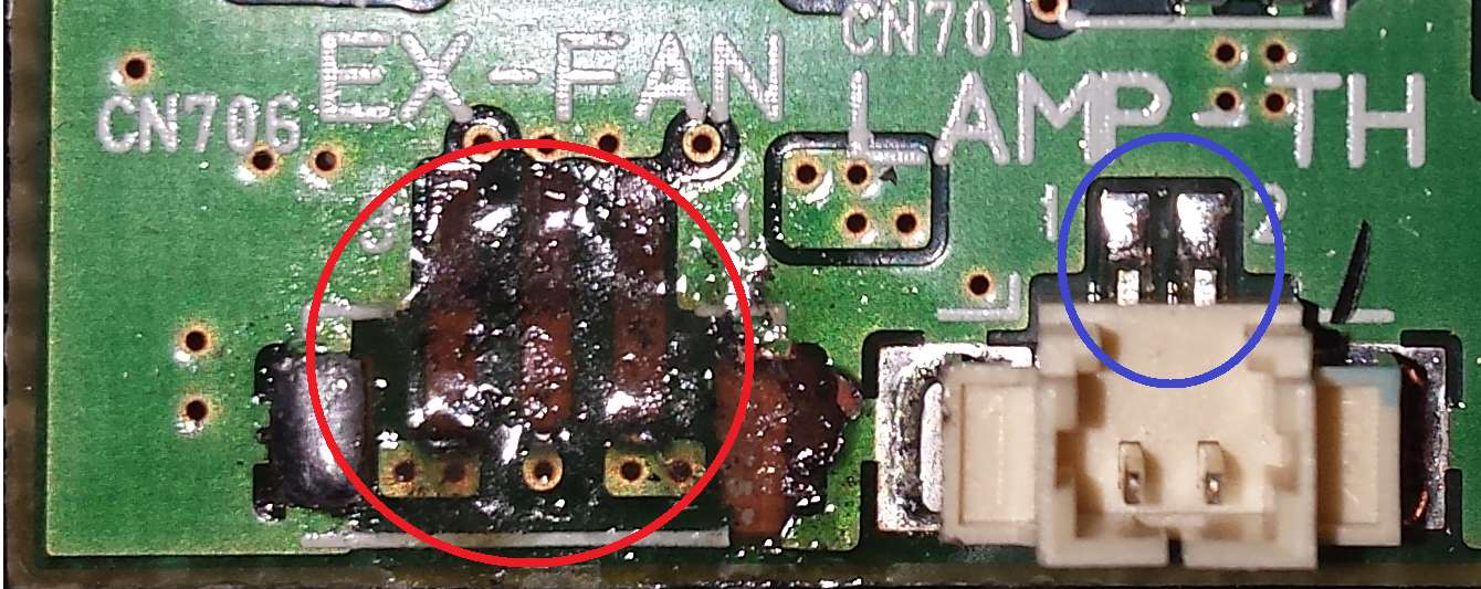
Ripped fan connector from mainboard

I want to ask you for a favour. I was disassembling this projector and unfortunatelly break off fan connector (3-pin) from the board. I was trying to solder the connector back but on the place is missing coating and It not hold. I soldered it to another place but the fan isn´t going and projector indicates high temperature (red diod).

Do anyone have any idea how to fix it? Is possible to solder only wires of the fan to the board (without connector)?

Thank you for your advices.

Blue circle shows a coating and red circle shows original place of connector

Block Image

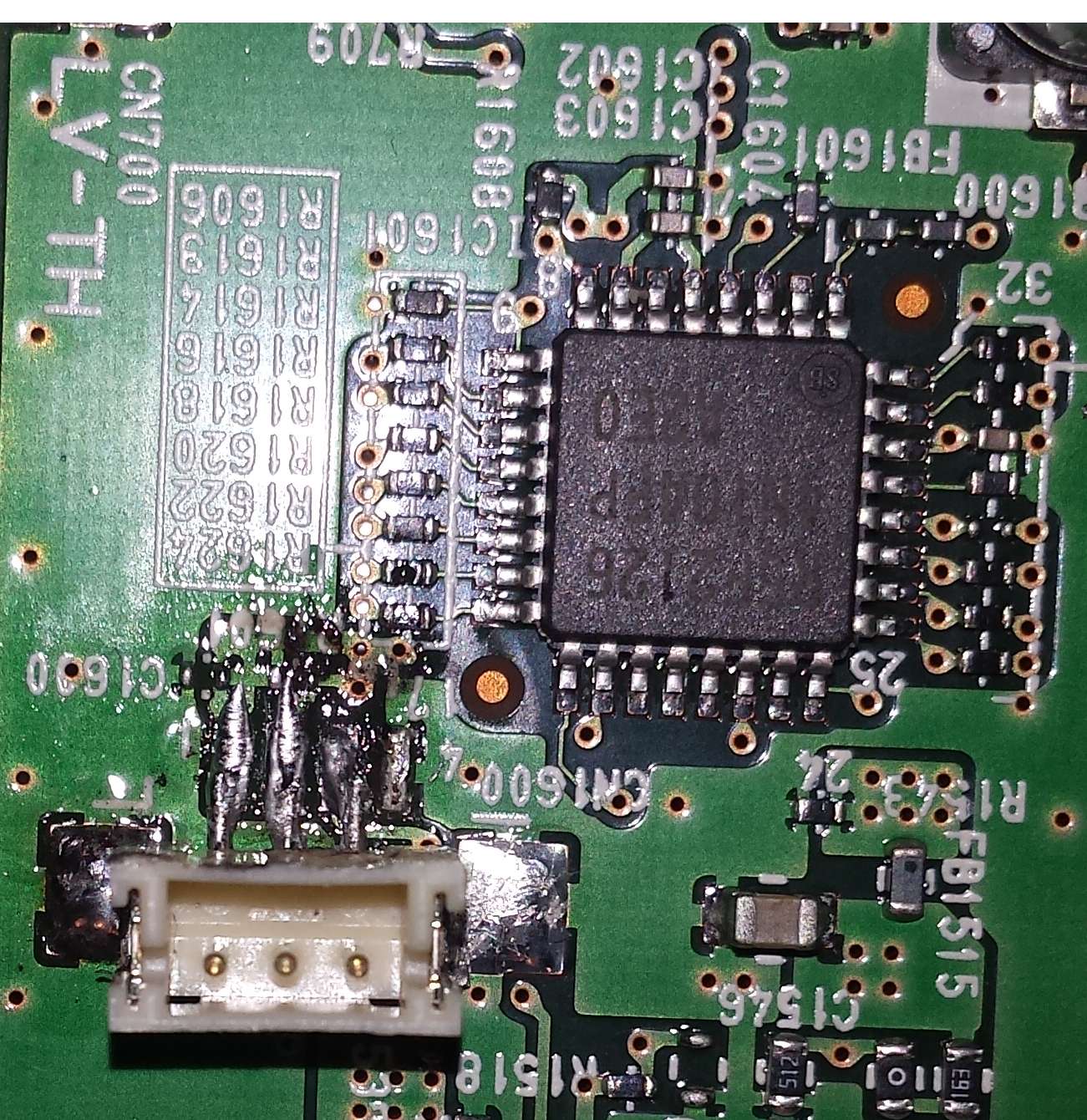
My idea to solve it which failed.

Block Image

Answered! View the answer I have this problem too

Is this a good question?

Score 0
2 Comments

Marhoon yes it is possible. I was wondering why you posted the second image. That is a different connector at a different location.

by

It is fan connector in different location

by

Add a comment

1 Answer

Chosen Solution

It's hard to say just based on the pictures...

Assuming the copper traces in (on or inside) the circuit board are still intact, I would opt to directly solder the wires to the pads at the bottom of the red circle. You could test those points with a multimeter to see if a voltage is present. You may need to scratch, very delicately, the solder mask (green layer) to expose some copper upon which you can solder. If you aren't already using solder flux, I highly recommend it.

If the traces are broken, you need to follow where the traces come from and then you could attach your fan there (you may need to lengthen your wires).

Was this answer helpful?

Score 2

2 Comments:

I tested 5 points and 2 of them are ok. Can I solder 2 wires to 1 point or I must follow traces? How can I do this? Will the fun work if I connect it to usb? Do you have some experience with this? Thank you a lot.

by

Hi @marhoon. Do you mean you tested the five "holes" at the bottom of your first picture? It appears that the two to the left are connected together, as are the two to the right. You can check continuity on them to confirm.

So in reality, you have three connections. Yes, you have to follow the wiring scheme. There is V+ wire, a GND wire and the third is probably a TACH(ometer) wire for controlling speed. Here is a good article http://www.pcbheaven.com/wikipages/How_P...

You will have to probe around to see what connects to where so that you can connect the wires. I do this quite a bit, you just have to be patient.

by

Add a comment

Add your answer

Marhoon will be eternally grateful.
View Statistics:

Past 24 Hours: 0

Past 7 Days: 0

Past 30 Days: 0

All Time: 169