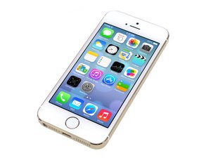
This is a very complex problem. Depending on the model, iPhone 5s may have 2 or 3 cellular antennas and 1 Wi-Fi/Bluetooth antenna.
The upper antenna UAT1 is the top portion of the metal band itself, serving low/mid band cellular diversity and GPS. It is connected to the logic board by contact pads near screw holes. It is connected to the ground by other metal parts and a small flex cable near the main camera.
The upper antenna UAT2 is behind the top glass piece of the rear case, it is a flex cable that connects to the back side of the logic board. Grounding is provided by the coaxial RF cable and the screw hole on the antenna itself. It serves as the Wi-Fi/bluetooth antenna. On Euro/Asian GSM models it also serves as the hi-band cellular diversity antenna.
The lower antenna LAT is a complex structure formed by the lower portion of the metal band, the lightning connector flex and some pieces of flex cables on nearby parts. It serves as the primary cellular antenna. The signal RF cable is connected to the lower portion of the logic board. There are control signals on the lightning flex to control antenna switches on the flex in order to dynamically adjust the performance of the antenna, so the antenna can work on low/mid/hi bands.
The cellular config of iPhone 5s is 2RX/1RX. Both the primary and diversity cellular antenna receives at the same time, but only one antenna can transmit at a time. The TX output is switched between UAT and LAT on the fly, depending on which antenna is less affected by your hand grip. LAT may have more complex switching logic to suit different RF performance/safety regulation requirements.
There are test connectors left on the logic board for debugging, I will update in the future.

 1
1  1
1 
 82
82