
1.6 or 1.8 GHz dual-core processor, 2 GB or 4 GB of SDRAM, 64 GB or 128 GB SSD

192 Questions View all

Can backlight of MB Air display be powered on w/o motherboard?

Hi to all electronic wizards,

my 11" 2011 Macbook Air display seemed cracked and had sort of a color bleeding growing from the crack, making it unusable. I swapped it with a new display using a great iFixit guide, so the computer is good as new.

The old display still has nice, even, white light (except from where the crack is, of course), and I thought it could be reused as a small slide sorter, as I have a project coming up where I will be sorting a couple of thousand slides, scanning the best ones.

Does anyone know if it is possible to light the LED backlight of the display without it being connected to a motherboard, for example just by supplying current to the right wires? I have little knowledge of electronics, but have soldered before and I think there is very little to loose here, anyway.

I was hoping someone could suggest a solution, or eventually tell me if this is totally hopeless.

All the best!

- Ivar

I can't align the text with the images, but they show:

- Overview

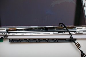
- LVDS cable, motherboard end (2 pics)

- LVDS cable and connector on circuit board in the screen

- Flat cable from LED strip

- Connector for LED strip cable

Block Image

Block Image

Block Image

Block Image

Block Image

Block Image

Answered! View the answer I have this problem too

Is this a good question?

Score 1
3 Comments

Hi again, I have found the part number for the LED strip in my screen. It is QT001A-S265-0G. I can't find a pinout. On the back of the inverter board (or the screen controller or whatever, I guess it's not an inverter board really) it says DCN202602L3DN57A5 LGD LP116WH4 TJA3 116B151401TAW 411A. Googling for LP116WH4 TJA3 tells me that I have an LG panel with this name, without backlight, meaning that the LED backlight is a separate part from the LCD. This link: http://www.panelook.com/LP116WH4-TJA3_LG... tells me that the signal interface to this LCD is eDP (1 lane), this is short for embedded display port, so it should be following a standard. I'm still hoping someone can help me sort this out, so I can power the LED backlight either through the LVDS cable, or directly to the flat connector on the LED strip.

All the best, Ivar

by

Ivar O, any chance for some Hires images of the board that is connected to your Display? Specially around the connector area.....

by

just an FYI:" the lack of standardization in the industry of LED backlight configuration and LED connectivity. Inside the backlight, there are some similarities in the way panel manufacturers configure the LEDs. This configuration tends to be in multiple banks of series-connected LEDs, but that is where the similarities end. Some manufacturers choose a common anode connection, some choose a common cathode configuration, and others choose a separate cathode and anode connection for each bank. This lack of standardization makes it difficult for designers to address the connectivity of LED drivers. The solution provided by some manufacturers is to add flexibility to support any and all of these configurations. from here

by

Add a comment

2 Answers

Chosen Solution

Ivar O, yes it absolutely is. I do that with old CCFL panels. Those make great reading lights:-) In order to get it accomplished we will need to at least have the number for the panel. I am certain that your will have an LCD backlight, so your power demands will be a lot less than the CCFL monitors. Post a couple images of your panel so we can see the wiring as well.

UPDATE

Okay so your LED driver is a LP8550 with these brief specs:

High-voltage DC/DC boost converter with integrated FET with four switching frequency options: 156/312/625/1250 kHz

2.7V – 22V input voltage range to support 1x…5x cell Li-Ion batteries

Programmable PWM resolution

-8 to 13 true bit (steady state)

-Additional 1 to 3 bits using dithering during brightness changes

I 2C and PWM brightness control

Automatic PWM & current dimming for improved efficiency

PWM output frequency and LED current set through resistors

Optional synchronization to display VSYNC signal

6 LED outputs with LED fault (short/open) detection

Low input voltage, over-temperature, over-current detection and shutdown

Minimum number of external components

Micro SMD-25 package, 2.466 x 2.466 x 0.6 mm

This will help us to determine what voltage you need for the input.

Further parameters of this IC are :

Vin (Min) (V) 5.5V

Vin (Max) (V) 22

Vout (Max) (V) 40

Iout (Max) (A) 400

Shutdown Current (Typ) (uA) 1

Iq (Typ) (mA) 4

LED (#) 60

LED Configuration series

LED Current Per Channel (mA) 30

Here is one way to build a driver circuit for your LED backlight

Block Image

Next is an image of your LCD connector. Pin 6-11 are the backlight connections

Block Image

This is where the importance of your LVDS cable comes in handy. You can now either traces the wires from your connector to the panel, or use the connector and purchase the female part that is usually on the logicboard, to build your driver. the connectors are available at places like this as well as many others

So, again, you could use the IC typical application, or you could emulate the backlight driver circuit that your computer uses. Here is the schematic for that.

Block Image

There is another thing you could do. That is to get a commercially available DC-DC converter that is capable of producing the proper voltages. Those are pretty much available at ebay.com as well as many other places. Then connect that to your panel using the pins as specified.

This is definitely a great project to continue to use old LCD panels.

Hope this helps, good luck.

Was this answer helpful?

Score 2

6 Comments:

Thank you oldturkey03, that sounds promising!

They are selling the display unit here at iFixit, here is one: MacBook Air 11" (Mid 2011) Display Assembly

I will crack mine open and take a few pictures. As it is now, there at four wires coming out of the unit, three out of the left hinge (two thin ones to the wi-fi antenna, and a small flat connector to the camera) and one bigger flat connector out of the right hinge, which is the display data cable. There are pictures of it beeing loosened from the motherboard in the iFixit guide to change the display assembly (see step 20): MacBook Air 11" Mid 2011 Display Assembly Replacement

I think that cable is also called an LVDS cable. I’m guessing power to the backlight also goes in that cable. I’ll post pics as soon as I have the time! Of course, it would be a plus to open up the display as little as possible.

- Ivar

by

You will need some of the wires on the LVDS cable, they are for the LED backlight. Once we know which panel you have, I can give you more information. The WiFi as well as the camera can later on be neglected. A few images and the number from the back of your panel should be all we need, to come up with a driver for the LED's. Looks like pin 1 through 12 on the display adapter are for the backlight function.

by

Hi, I have now taken the thing apart. I removed the black plastic bar at the bottom (WiFi antenna), and also the iSight camera (planning to recycle the camera in another project - from what I have read, it’s just a standard USB camera).

The LCD itself was broken, you can see the cracks in the picture. The LCD liquid was seeping out, and I managed to both split it in two sheets and break it somewhat along the edges during removal. The LCD connects to the small circuit board near the bottom of the assembly (inverter board?) via two flat, orange cables. Since I’m not using the LCD, I’m guessing I can just cut these. I think I will just replace the LCD with a thin plastic sheet, to protect the diffuser.

The diffuser also got damaged, with some scratching around the edges, but it will still be fine for my purpose.

by

(... continued) In addition to the flat plastic cables, that must be data cables to the LCD, the circuit board connects to the LVDS cable, and to a small, flat cable that goes to the backlight.

You ask for the number from the back of the panel. The numbers I can find are the following:

On the back of the inverter board: DCN202602L3DN57A5 LGD LP116WH4 TJA3 116B151401TAW 411A. On a label on the lid, under the inverter board: RDTG21Y0180LG1K990126. I don’t know if there’s anything under the backlight, but I don’t want to check before you tell me that I really have to! Is there any other info you need?

I will post pictures when I figure out how to do it.

by

Thank you, oldturkey03!

I'm really impressed by your research and your help. This is slightly above my level, I think, but I will see if I can get it to work. It is a nice project, as you say. If I can make it work, I'll post it here (but don't hold your breath, it will take me some time for sure).

Thank you again!

All the best from Ivar.

by

Show 1 more comment

Add a comment

How come the LCD connector here is 40 pins, when I have count only 30 pins ??

Was this answer helpful?

Score 0

1 Comment:

Give us the last four digits of your computers serial number. This will help us to properly identify your computer/logicboard and we can try and figure it out.

by

Add a comment

Add your answer

Ivar O will be eternally grateful.
View Statistics:

Past 24 Hours: 0

Past 7 Days: 0

Past 30 Days: 11

All Time: 2,926