Fixing Mac mini power switch?
Hi,
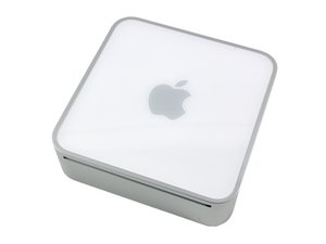
I've acquired a Late 2009 Mac mini that will not turn on at all. I believe the problem to be a broken power switch. The connector coming off of the power button is broken.
Pictures (link to all):
- What the connection is supposed to look like: http://imgur.com/U4HOgLD

- The leads from the power switch: http://imgur.com/hRrVplH

- The place the connector is supposed to go: http://imgur.com/xtZBUz8

- A ghetto solution that doesn't seem to work: http://imgur.com/IiSEuC5

The connector on the logic board appears to be labeled J4801.
Is there some way to solder this up? Can I buy a replacement switch? I would love to hear any suggestions or advice!
Thanks!
Update (2013-06-04)
Actions taken since last time
I have removed the internal frame assembly, RAM, and wireless card, as I have read that they may be a source of problems. In an effort to better understand the situation, I've also busted out the multimeter. Here's what I've found.
How the power button works
When I connect the leads from the ohmmeter to the leads from the power button (visible in picture 2) and hit the power button, the ohmmeter reads a low resistance. From this, I infer that the power button works by connecting the two little pins in the power connector (visible in picture 3) together.
Simulating the power button
I should be able to power the system on by connecting those two pins (from picture 3). So I took the leads from the ohmmeter and attempted to touch one to each of the aforementioned two pins (from picture 3). To the best of my vision, I think I am touching each pin with the ohmmeter, but it still reads an infinite resistance.
Edit: This is not correct. See the update from 2013-06-05.
Questions
(A) When connected to the power connector's pins (seen in picture 3), shouldn't the ohmmeter be reading a low resistance? Isn't the function of the power button to close a circuit that is open because the power pins (from picture 3) are not touching?
Edit: I've figured out the answer to this. See the update from 2013-06-05.
(B) Are there any useful readings I can take with the multimeter to test various components?
Please respond; I'd love to hear your thoughts!
Update (2013-06-05)
How the power button works
I wasn't 100% right. It's a momentary switch (some information on those). But I came to the right conclusion: touching the two pins from picture 3 together should simulate hitting the power switch.
What I've tried
As I mentioned earlier, I also tried using an ohmmeter to indirectly touch those pins together. That was dumb, because ohmmeters put out a voltage. That answers Question (A) from my update yesterday.
A few days ago, I had tried using two paperclips to short those pins, but that didn't do anything. So I tried using an ammeter to short the pins, but that also did not work.
Questions
Question (B) from the 2013-06-04 update remains: Are there any useful readings I can take with the multimeter to test various components?
Thanks for taking the time to read this! I would appreciate hearing any thoughts you have!
Is this a good question?

 1
1
Hi Sam, good job documenting all of this! What follows is my guess based on what I know of my old iMac. What you've said about it being a momentary switch seems right; have you tried turning it on by forming a conductive path across those two parts? If the Mini starts up, you've found your problem! If not, I would suspect deeper logic board involvement...
by Adam Hintz
Thank you for your response! Not sure if I'm responding to your comment properly, but here goes.
Yes, I've attempted creating a conductive path across the pins on the power socket (seen in picture 3) both with an ammeter and with paper clips. Neither have worked. My next course of action is going to be removing the bottom housing and trying to short the pins again.
by sam
Which power adapter are you using with this? The PowerPC minis used an 85W adapter whereas the later Intel powered minis required a 110W adapter. The 85W would provide enough power to show some readings but IIRC you won't see any signs of life (hard drive noise, fan movement, lights) until you use the 110W.
by LikeARabbit
On my Mini, the power switch connector sheared right off the solder pads while reconnecting it after replacing dried-out heatsink compound. I was able to use a regular soldering iron to re-tin the pads on the board and the connector pins (still attached to the wire) and then a brief touch of the ends to the pads while heated with the iron fixed them firmly in place. The mini powered right up.
Note there are four solder pads for the connector, but only TWO have a function. They are labeled "V" and "J4801". The other two do nothing. They are just there to provide anchor points for the connector. Solder the wires back to the two labeled pads. I used the natural orientation of how the wires and broken connector would lie to determine which wire went to "V", tagged that one, and worked back from there. Some switches have diodes or hall-effect sensors, which may require correct polarity an I only wanted to do this once!
by EF Conrad