Janet, first off, here is a good list of explosion drawings for your engine. Now as for how to do that, here are the instructions from Briggs & Stratton:"
Before the cylinder head can be removed, other external parts must be removed, such as the air cleaner, fuel tank, oil fill tube, blower housing, muffler, carburetor, control bracket assembly, and intake manifold.
Remove Cylinder Head
Horizontal and Vertical Models 97700,99700, 110000, 120000, 150000
1. Remove four screws (A, Figure 1 or 2)from rocker cover, then remove cover and
gasket.
2. Remove cylinder head screws (Figures 3), then remove head and gasket
from cylinder.
3. Remove push rods one at a time, marking the location and orientation of each for
proper installation later.
4. Using a plastic scraping tool, carefully clean all traces of head gasket from the
head and cylinder mating surfaces.
Disassemble Cylinder Head
1. Loosen rocker arm screws and/or lock nuts (A, Figure 7 and 8), and remove from
rocker arm studs. Remove rocker arms (B) and rocker balls from studs.
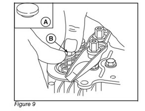
2. Remove valve stem caps (A, Figure 9) (if used), the rocker arm studs, and the push rod guide (models 97700, 99700).
3. Using thumbs, press down on each valve spring retainer and disengage retainer from valve stem (B). Remove retainers, springs, valves, and intake valve stem seal/washer, if equipped.
4. Remove push rod cylinder head plate and plate gasket (models 110000, 120000,150000). Remove and discard the plastic push rod guides from the head plate.
Inspection
1. Visually inspect head for cracks,excessive heat discoloration, warping of the cylinder or rocker cover mating surfaces, and burned or damaged valve seats. Replace head, if any of these problems are found.
2. If head passes visual inspection, use Plug Gauge #19122 to check valve guides for wear. If gauge enters the guide 1/4” (6.4mm) or more, replace the guide (models 97700, 99700) or replace the entire head (models 110000, 120000, 150000). If plug gauge is not available, see Section 12 -Engine Specifications for the valve guide reject dimension.
NOTE: To replace valve guides (models 97700, 99700), use Valve Guide Driver #19367 (A,Figure 10) to press out the guides. Then, using the same tool, press either end of the new guides into the head until 1/8” (3.2 mm) above flush (A,Figure 11).
3. If guides are replaced, or the original guides still meet specifications, use Finish Reamer #19066 and Reamer Guide #19191 to ensure proper sizing and to clean out the guides. Thoroughly clean all reaming debris from cylinder head.
4. Inspect valves for wear or damage.Replace if necessary.NOTE: Valve faces can be resurfaced on a commercially available valve grinder. However, Briggs & Stratton does not recommend this practice because the quality of the resurfacing may be insufficient. Instead, valve replacement is recommended.
5. Oil the intake valve guide and intake valve stem, then insert valve into head.
6. Using Valve Lapping Tool #19258 and Lapping Compound #94150, lap valve and seat together to assure a good sealing surface. Remove valve, the repeat procedure for the exhaust valve.
7. Thoroughly clean both valves and cylinder head of all lapping compound residue.
Assemble Cylinder Head
1. Install new plastic push rod guides into the cylinder head plate (A, Figure 12) (models 110000, 120000, 150000). Using new plate gasket, install the cylinder head plate. Torque screws to values listed in Section 12 - Engine Specifications.
2. Lightly coat valve stems with Valve Guide Lubricant #93963. then insert valves into cylinder head. Do not get lubricant on valve face, valve seat, or exposed end of valve stem.
3. Oil inside diameter of new stem seal/washer and install on intake valve stem. Slide seal down against head plate or cylinder head (A, Figure 13).
4. Support valve side of cylinder head on clean shop rags. Place valve springs and valve spring retainers over valve stems. Using thumbs, press against each retainer until it securely locks into groove in valve stem (Figure 14)
Install Cylinder Head
1. Coat threads of all cylinder head screws with Valve Guide Lubricant #93963.
2. Using a new head gasket, install cylinder head on cylinder and start screws by hand. Step-torque screws in sequence shown (Figures 15, 16, 17, 18) until final torque value is achieved. Torque screws to value listed in Section 12 - Engine Specifications.
NOTE: Do not torque each screw in one step as it may result in a warped cylinder head. Steptorque all screws to approximately 1/3 of final torque value, then to 2/3 final torque value, then finish at final torque value.
3. Install push rod guide and rocker arm studs (models 97700, 99700). Torque studs to values listed in Section 12 -Engine Specifications.
-OR-
4. Install rocker arm studs (models 110000,120000, 150000). Torque to values listed in Section 12 - Engine Specifications.
NOTE: Early production of vertical models 110000 and 120000 require a jam nut to be threaded approximately half way up the threads of the stud before installation into the head.
5. Install push rods through guides and into same positions as removed. Ensure rods are seated in valve tappets. Place valve stem caps (if used) on valve stems.
6. Place rocker arms and rocker balls on rocker arm studs (Figure 19). Install rocker arm screws and/or lock nuts on studs and tighten until there is zero clearance between the valve stem caps and the rocker arms.
7. Rotate crankshaft at least twice to ensure proper movement of the push rods and rocker arms.
8. Adjust valve clearance per Section 1, then install a new rocker cover gasket and the rocker cover. Torque screws to values listed in Section 12 - Engine Specifications.
ENGINE SPECIFICATIONS
Armature Air Gap .010 - .014 in. (.25 - .36 mm)
Crankshaft End Play .002 - .028 in. (.05 - .71 mm)
Spark Plug Gap .030 in. (.76 mm)
Valve Clearance – Intake .004 - .006 in. (.10 - .15 mm)
Valve Clearance – Exhaust .009 - .011 in. (.23 - .28 mm)
CYLINDER HEAD STANDARD SIZE REJECT SIZE
Valve Guide .249 in. (6.32 mm) .267 in. (6.78 mm)
Intake Valve Stem Diameter .247 in. (6.28 mm) .244 in. (6.20 mm)
Exhaust Valve Stem Diameter .247 in. (6.28 mm) .244 in. (6.20 mm)
These instructions read more complicated then the job really is. Email me if you need a copy of the manual. Also, just to make sure that it is your valves that give you trouble, I recommend a compression test or a leak down test. It will tell you a bit more. Use the tester manual (you can get those at most automotive supply places) to do the test. Hope this helps, good luck.


2 Comments
Janet, yes it is entirely possible. But there are also a few other possibilities. If at all possible, could you provide us with the model number of the engine? It might help to narrow it down a bit. Could you do the repair yourself? It depends how handy you are, but it most certainly is possible.
by oldturkey03
Im am pretty good at taking things apart and putting them back together right. No matter what it is. I have not done as much engine work as I would have liked to, but I believe I could do it. As long as its together right in the first place, lol. The engine model number is 121602-0190-E2-000628 FA
by Janet