PlayStation 3 Teardown

Teardown

Teardown

Teardowns provide a look inside a device and should not be used as disassembly instructions.

Featured Guide

Featured Guide

This guide has been found to be exceptionally cool by the iFixit staff.

User-Contributed Guide

User-Contributed Guide

This guide is not managed by iFixit staff.

  • Add Note x

This is a teardown of an original launch 60GB PlayStation 3 system. One of the best units out there that had backwards compatibility and the card readers. Sadly this unit has a GPU a problem so it's broken.

Edit: Nickname fix, formerly Karasumachitose. Apologies to any inconvenience this causes.

first image
thumb image 1
thumb image 2
thumb image 3

Add Note Edit Step 1 — PlayStation 3 Teardown  ¶ 

  • There she is, one of the two original PS3 models available at launch (60GB).

  • It's got PS2/PS1 backwards compatibility and a multi-card reader. The current PS3 Slim doesn't have either. The other launch model lacked the card reader and WiFi (20GB).

first image
thumb image 1
thumb image 2

Add Note Edit Step 2  ¶ 

  • Let's get started!

  • Remove the hard drive access cover from the bottom of the PS3.

first image

Add Note Edit Step 3  ¶ 

  • Use the Phillips screwdriver #1 to remove the blue screw.

first image
thumb image 1
thumb image 2
thumb image 3

Add Note Edit Step 4  ¶ 

  • Lift up the metal lever.

  • Slide the hard drive towards the front of the case.

  • Pull it straight up and out of the unit.

    • This is all you need to do to access the PS3's hard drive.

first image
thumb image 1
thumb image 2
thumb image 3

Add Note Edit Step 5  ¶ 

  • Remove the warranty sticker.

    • Obviously this voids your warranty. You have been warned.

  • Use your fingers and pry up and remove the foot underneath the sticker.

first image
thumb image 1
thumb image 2

Add Note Edit Step 6  ¶ 

  • Use the Torx Screwdriver (T8 or T10) to remove the torx screw from the space behind the rubber foot.

    • This screw has a security bit but most are able to remove it successfully with a normal Torx driver.

first image
thumb image 1
thumb image 2
thumb image 3

Add Note Edit Step 7  ¶ 

  • Place Playstation face up such that "Playstation 3" is oriented so you can read it.

  • Place your palm on the Playstation 3 logo and slide the plastic front cover towards you and off of the outer plastic shell. Set it aside.

first image
thumb image 1
thumb image 2
thumb image 3

Add Note Edit Step 8  ¶ 

  • Remove the metal receiver that held the torx screw you just removed.

first image

Add Note Edit Step 9  ¶ 

  • Remove the 9 screws from the outer plastic shell using a #2 Philips driver.

    • 6 large screws

    • 1 medium screw

    • 2 small screws

first image
thumb image 1
thumb image 2
thumb image 3

Add Note Edit Step 10  ¶ 

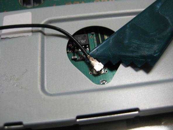
  • READ THIS ENTIRE STEP AND THE NEXT ONE BEFORE PROCEEDING. Locate the two locking tabs on the back of the PS3. Push them in simultaneously and lift the outer plastic shell off of the main board but BE CAREFUL as there is a ribbon cable connecting the shell to other hardware.

    • Ribbon cables are very fragile. Take care when removing or inserting ribbon cables.

first image
thumb image 1
thumb image 2
thumb image 3

Add Note Edit Step 11  ¶ 

  • Disconnect the ribbon cable and set the shell aside.

first image
thumb image 1
thumb image 2
thumb image 3

Add Note Edit Step 12  ¶ 

  • To remove the plastic card reader, locate its two locking plastic tabs that hold the card reader to the shell, spread them, and lift the card reader off of the shell.

first image
thumb image 1
thumb image 2
thumb image 3

Add Note Edit Step 13  ¶ 

  • Working on the main unit, lift up on and disconnect the black RF wire from the wireless assembly using a spudger.

first image
thumb image 1
thumb image 2

Add Note Edit Step 14  ¶ 

  • Remove the flat ribbon cable from the wireless assembly.

first image

Add Note Edit Step 15  ¶ 

  • Remove the four Philips #2 screws from the top of the wireless assembly.

first image
thumb image 1
thumb image 2
thumb image 3

Add Note Edit Step 16  ¶ 

  • Lift the wireless assembly off the main board and set it aside.

  • Disconnect the ribbon cable from the main board and place it with the wireless assembly.

first image
thumb image 1
thumb image 2
thumb image 3

Add Note Edit Step 17  ¶ 

  • Locate the other wireless assembly which the black RF wire is connected to.

  • Remove the one Philips #2 screw retaining it to the main board and lift off the assembly and set it aside.

first image
thumb image 1
thumb image 2

Add Note Edit Step 18  ¶ 

  • Remove the cables that attach the power supply to the main board.

  • Remove the AC connector from the power supply.

first image
thumb image 1
thumb image 2
thumb image 3

Add Note Edit Step 19  ¶ 

  • Remove the 5 screws using a Philips #2 from the power supply, and lift the power supply straight up and off of the main body. Set it aside.

    • There are 2 power pins connecting the motherboard to the power supply as you remove it.

first image
thumb image 1
thumb image 2

Add Note Edit Step 20  ¶ 

  • The screws holding the blu-ray drive to the main board have already been removed in a previous step.

  • Unplug the power connector (gray) on the side of the player.

first image
thumb image 1
thumb image 2

Add Note Edit Step 21  ¶ 

  • READ THIS ENTIRE STEP BEFORE PROCEEDING. Lift the player up slowly to expose the folded ribbon cable beneath it.

  • Remove that ribbon cable from the main board and set the drive/cable aside.

first image
thumb image 1
thumb image 2

Add Note Edit Step 22  ¶ 

  • Remove the ribbon cable attaching the on/off and eject switch circuit board to the main board.

first image
thumb image 1
thumb image 2
thumb image 3

Add Note Edit Step 23  ¶ 

  • Remove the 4 Philips #2 screws retaining the circuit board to the case.

  • Remove the circuit board from the case.

No image

Add Note Edit Step 24  ¶ 

  • These screws are med size, different from most the other Phillip #2s

first image
thumb image 1
thumb image 2

Add Note Edit Step 25  ¶ 

  • Remove the 9 screws from the main body.

    • 5 Medium Philips #2 Screws

    • 2 Small Philips #1 Screws

    • 1 Ground Philips Screw with Washer

    • 1 Bolt Philips Screw (under AC cord)

first image
thumb image 1
thumb image 2

Add Note Edit Step 26  ¶ 

  • Grab the main board at the locations shown in the picture and lift the main board off of the back casing.

  • Set aside the black shell.

first image
thumb image 1
thumb image 2
thumb image 3

Add Note Edit Step 27  ¶ 

  • On the main body, locate the 5 plastic locking tabs holding the rear plastic I/O shield to the main body.

  • Pry the tabs away from the body and lift the rear shield away.

first image
thumb image 1
thumb image 2
thumb image 3

Add Note Edit Step 28  ¶ 

  • Remove the fan power connector.

first image
thumb image 1
thumb image 2
thumb image 3

Add Note Edit Step 29  ¶ 

  • Remove the 3 Philips #2 screws holding the fan to the main body.

    • These are extra small screws

  • Lift the fan straight up and out of the body.

    • Check out the size of this thing.

first image
thumb image 1
thumb image 2
thumb image 3

Add Note Edit Step 30  ¶ 

  • On the top of the mainboard, EVENLY remove the four large Philips #2 screws holding the heat sink.

    • Removing them evenly reduces strain on the GPU and CPU.

  • Remove the plates and the screws from the main board.

first image
thumb image 1
thumb image 2
thumb image 3

Add Note Edit Step 31  ¶ 

  • Flip the main board over.

  • Lift (or pry with fingers) the heat sink straight off of the mainboard and processors.

  • Force will be required as the thermal paste "glues" the heat sink to the processor.

  • Note: If new thermal paste is readily available, clean the old paste off well and apply new thermal paste at the time of reassembly. If new thermal paste is not available or you are cheap, do not disturb the "old" thermal paste.

first image
thumb image 1
thumb image 2

Add Note Edit Step 32  ¶ 

  • Remove the 2 Phillips #0 screws from the hard drive enclosure.

first image
thumb image 1
thumb image 2

Add Note Edit Step 33  ¶ 

  • To expose the mainboard, remove the watch battery from the mainboard.

first image
thumb image 1
thumb image 2
thumb image 3

Add Note Edit Step 34  ¶ 

  • Using spudger, carefully pry the metal shielding away from and off of the top of motherboard.

first image
thumb image 1
thumb image 2
thumb image 3

Add Note Edit Step 35  ¶ 

  • Turn the motherboard over and remove the metal shielding on the opposite side. Pry with a spudger or with your fingers.

first image
thumb image 1
thumb image 2

Add Note Edit Step 36  ¶ 

  • Check out all the chips with heatspreaders on this thing.

    • There's the Emotion Engine chip and Graphics Synthesis chip that allows the sweet backwards compatibility.

    • IBM Cell processor... This CPU has 9 cores, 10 threads and it runs @ 3.2GHz which makes it very powerful.

first image
thumb image 1
thumb image 2
thumb image 3

Add Note Edit Step 37  ¶ 

  • More Chips!

  • IBM Cell Processor

  • Nvidia RSX

first image
thumb image 1
thumb image 2

Add Note Edit Step 38  ¶ 

  • Consider your PS3 disassembled.

Notes Add Note Notes are offturn on