Introduction
This is a Sony MZ-R700 minidisc, Sony's attempt to provide an alternative to portable CD players, right before the mp3 revolution. Minidiscs were particularly popular in Europe and Asia but the devices didn't catch on as much in North America. This model supports MDLP and was capable of recording up to 4 full-length audio CDs onto one small minidisc (via Sony's proprietary ATRAC format).
What you need
-
-
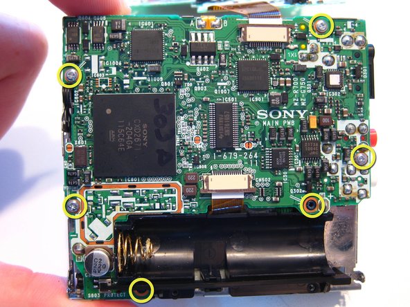
Start by removing the 8 very small screws on both sides of the unit. The front door will still be connected via the latch.
-
-
-
-
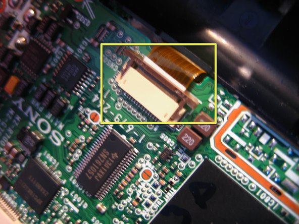
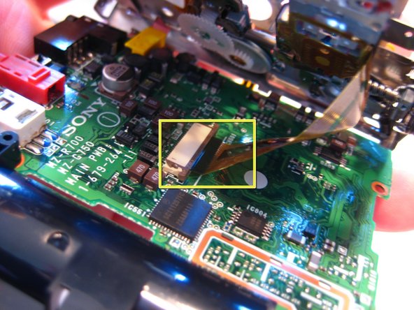
Next, remove the front panel from the main part of the unit. The ribbon cable connects the two. To remove, gently pull out the dark brown connector from both sides of the beige holder. This will release the ribbon cable which can then be pulled out and separated. There are three in total, two on the outside, one under the battery case and one on the lower part of the unit. The third one is on the inside of the unit.
-
-
-
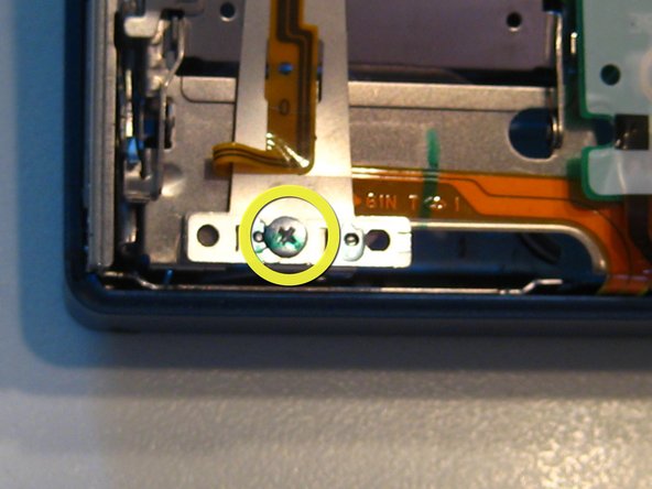
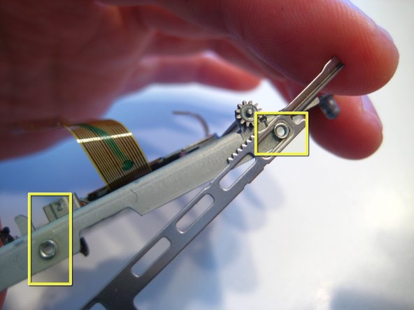
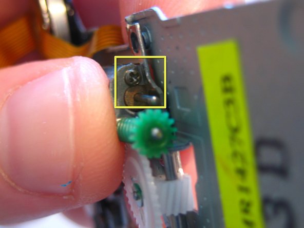
Gently pry the door away from the metal enclosure. Next, remove the bar on the side of the enclosure. Pry a flathead screwdriver between them and gently remove it. Finally, remove the black gear (above the green one, removed here) which will reveal one more, tiny screw that needs to be removed. At this point you may remove any remaining latches connected to the unit. Simply pry with a small flathead screwdriver and remove them.
-


4 Comments
Why would you do that?
Have you put it back together?
Does it work?
Thank you! Used this guide to open my R700 :)
Richard Harris: Probably so that you can replace one of those parts in the event one of them is broken
Fine. However, the biggest problem with Sony MD players/recorders is the unavailability of the dedicated rechargeable batteries they require for use as independent units.