Introduction
Here's a Sony wireless stereo earphone system consisting of an infrared transmitter and receiver pair, dating from around 1993. At that time, there was no such thing as an iPod and so the smallest personal audio players were cassette tape Walkmans or compact disc Discmans. With this wireless earphone kit, you could listen to your stereo, free to wander around the room without one of those 10 foot headphone cords or without a relatively bulky audio player attached to your belt.
Of course nowadays, you can have thousands of songs in an even smaller device attached to your shirt sleeve, so this kind of audio accessory is not so interesting any more for most consumers. However, this same basic technology is still in use in many places - for example some auditoriums will have large IR arrays providing wireless audio to the hearing impaired in the audience.
Let's take it apart to see what's inside...
What you need
-
-
The main components of this kit are:
-
TMR-IF33 wireless transmitter
-
IFR-33 wireless receiver
-
9V DC output AC adapter
-
Set of headphones
-
I'm not sure if this product was sold in North America, this one was purchased in Japan. In the second photo you can see the original packaging.
-
I do know that Sony used the same IR transmission system in some of its North American TVs - these components work with the wireless headphones that came with my old XBR TV.
-
-
-
The transmitter has a stereo audio mini-jack input, stereo RCA jack inputs, and a 9V DC input jack. On the bottom there is a switch for normal/surround sound.
-
On the back you can see some keyed mounting holes for optional wall-mounting ofthe transmitter.
-
We'll take this transmitter apart first...
-
-
-
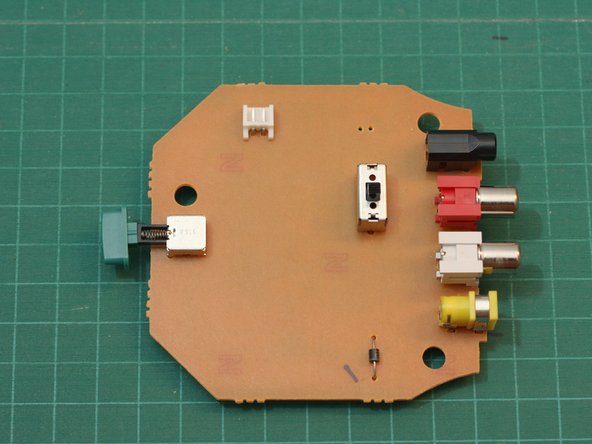
Carefully disconnect the connector shown from the circuit board. The wires go to the infrared LED array, which we'll see in a moment.
-
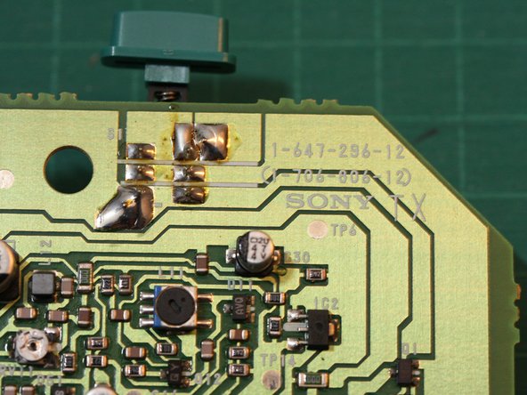
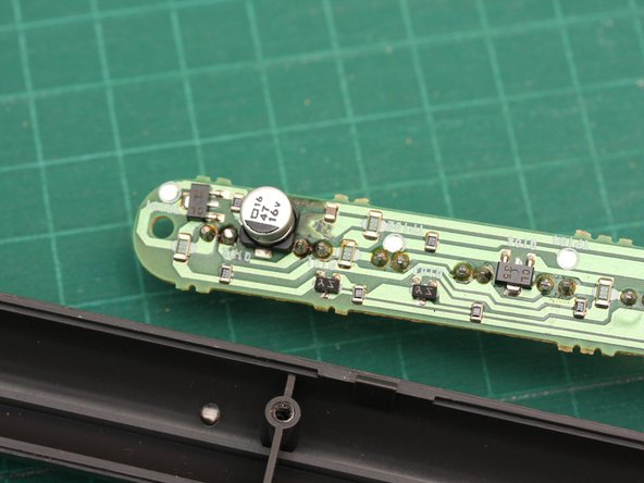
The circuit board on this side is very plain. The green button on the left is the power switch.
-
Hopefully there's more to the transmitter circuit than that lone diode visible on this side...
-
-
-
-
Next we'll open the housing for the IR transmitter array...
-
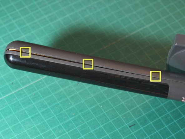
Using either your thumbnail or a spudger, carefully pry the housing open along the seam.
-
There are 3 hidden tabs on either side of the transmitter mast (see markers in 2nd photo). Pop these open carefully and the lens portion of the housing will come off.
-
-
-
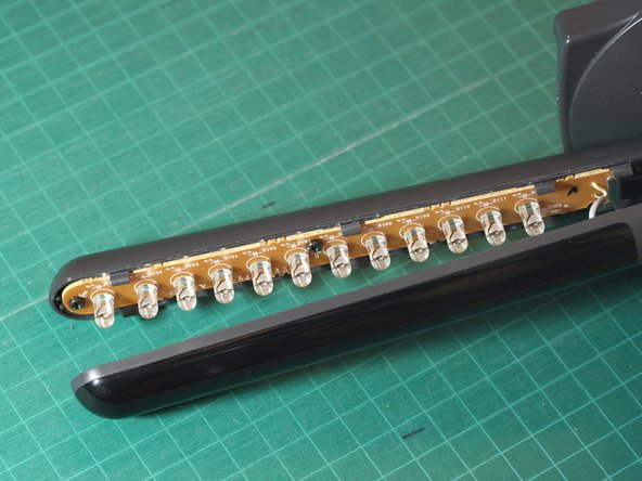
Here's the transmitter mast with the front lens/cover of the housing removed. Inside we see an array of infrared LEDs.
-
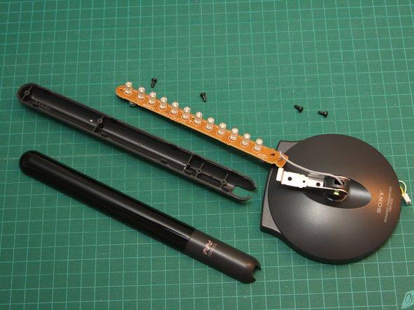
Next remove the 4 Phillips screws. Two of the screws fasten the metal hinge to the back half of the housing (one is partially obscured by the hinge in the first photo).
-
The other two screws fasten the LED circuit board to the back half of the housing.
-
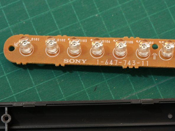
The third photo shows a closer view of some of the infrared LEDs. There are 12 LEDs in all. They emit no visible light - but did you know? the IR beam can be seen by most camcorders and digital cameras.
-
-
-
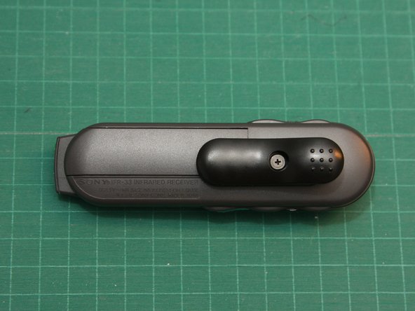
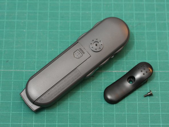
On the back, you'll find a swiveling clip and the battery compartment cover.
-
In use, the receiver can be clipped to your belt or shirt. The kit also comes with a lanyard (not shown) that let's you wear the receiver around your neck. Standard stereo earphones can be plugged into a jack at the bottom of the receiver.
-
The receiver is powered by a single AA battery.
-
-
-
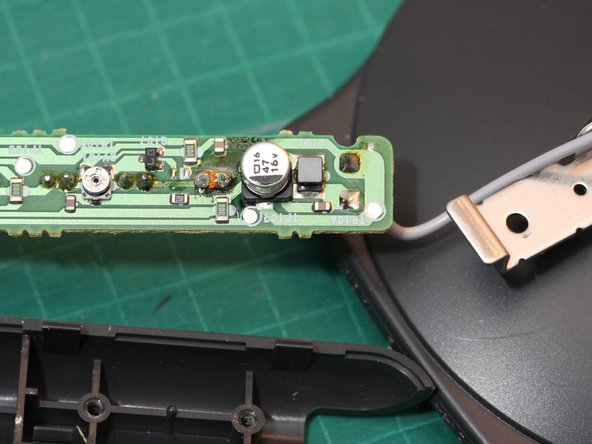
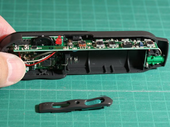
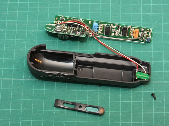
The receiver circuitry resides on two small circuit boards soldered together perpendicularly.
-
To remove the circuit board, first carefully pull the battery contact/spring up out of its mounting slot. This should free the circuit board.
-
The 3 wires connect the circuit board to the stereo earphone jack (green).
-
-
-
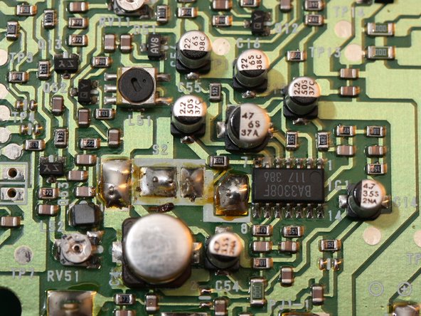
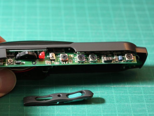
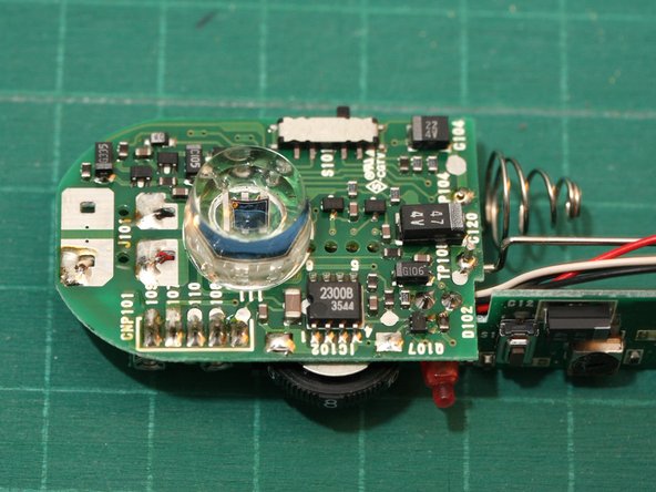
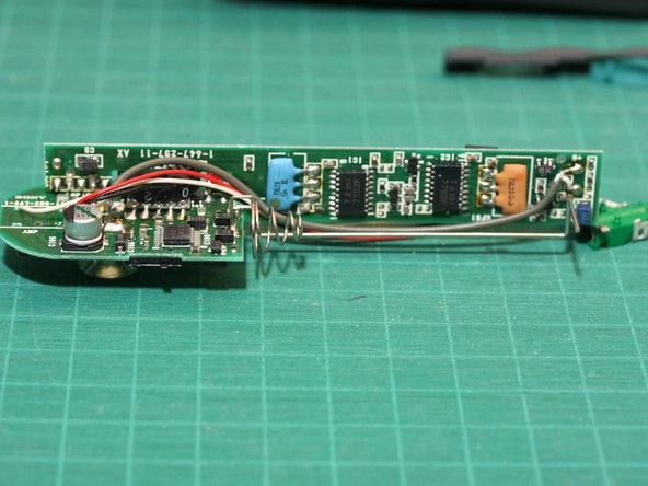
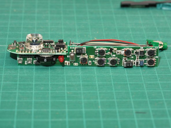
Here are a couple views of the receiver circuit board.
-
You can see the IR optical receiver under the large clear plastic lens. It's not obvious from the photos, but the cylindrical lens has a deeply concave front.
-
Once again, we notice mostly discrete components. The single IC in an 8 pin DIP package is a 2300B optocoupler chip.
-


One Comment
Bonjour, mon récepteur ne fonctionne plus. Je ne comprends pas l'anglais et ne suis pas capable en électronique !
Où pourrais-je l'envoyer pour réparation.
Merci beaucoup