
What you need

This teardown is not a repair guide. To repair your Sony Ericsson Xperia X10 Mini E10i, use our service manual.

  1. Sony Ericsson Xperia X10 Mini E10i Teardown, Sony Ericsson Xperia X10 Mini E10i Teardown: step 1, image 1 of 2 Sony Ericsson Xperia X10 Mini E10i Teardown, Sony Ericsson Xperia X10 Mini E10i Teardown: step 1, image 2 of 2
    • The Sony Ericsson Xperia X10 Mini E10i is the smaller version of the Sony Ericsson Xperia X10.

    • Tech Specs:

    • 600 MHz Qualcomm MSM7227

    • 256 MB RAM and 256 MB internal ROM (only 128 MB accessible)

    • 2.6" color transflective TFT display with a resolution of 240 X 320 pixels.

    • 5 Megapixel camera with autofocus

    • 802.11 b/g Wireless + Bluetooth 2.1

    • The backside of the X10 Mini E10i is characterized by a smooth plastic rear case with openings for the camera, LED flash, and speaker.

  2. Sony Ericsson Xperia X10 Mini E10i Teardown: step 2, image 1 of 3 Sony Ericsson Xperia X10 Mini E10i Teardown: step 2, image 2 of 3 Sony Ericsson Xperia X10 Mini E10i Teardown: step 2, image 3 of 3
    • The controls of the X10 Mini E10i are pretty standard.

    • The bottom of the X10 Mini E10i integrates a 3.5 mm headphone jack as well as a micro-USB port.

    • The top edge houses the power button.

    • The left side accommodates the volume and camera buttons, leaving the right side blank and featureless.

  3. Sony Ericsson Xperia X10 Mini E10i Teardown: step 3, image 1 of 2 Sony Ericsson Xperia X10 Mini E10i Teardown: step 3, image 2 of 2
    • The 5.0 megapixel camera in the X10 Mini E10i features a 1X optical zoom with autofocus and a built-in LED flash.

    • The camera itself measures in at 8.8 x 9.1 x 6 mm.

  4. Sony Ericsson Xperia X10 Mini E10i Teardown: step 4, image 1 of 3 Sony Ericsson Xperia X10 Mini E10i Teardown: step 4, image 2 of 3 Sony Ericsson Xperia X10 Mini E10i Teardown: step 4, image 3 of 3
    • A few quick pries with an iPod opening tool around the perimeter of the X10 Mini E10i and the rear case easily pops off to access the phone's innards.

    • The actual electronic volume and camera buttons are attached directly to the logic board. The buttons you press on the outer case are just chrome covers.

  5. Sony Ericsson Xperia X10 Mini E10i Teardown: step 5, image 1 of 1
    • A thumbnail is all that is needed to remove the microSD card from its housing in the inner case.

    • The simple design of the Mini E10 allows most components to plug directly into the logic board. The only exception is the external microSD card slot.

  6. Sony Ericsson Xperia X10 Mini E10i Teardown: step 6, image 1 of 2 Sony Ericsson Xperia X10 Mini E10i Teardown: step 6, image 2 of 2
    • A single T5 Torx screw and a few plastic clips are all that secure the antenna assembly to the inner case.

    • The antenna assembly uses simple yet effective pressure contacts to make a connection with the logic board. No connectors necessary!

  7. Sony Ericsson Xperia X10 Mini E10i Teardown: step 7, image 1 of 3 Sony Ericsson Xperia X10 Mini E10i Teardown: step 7, image 2 of 3 Sony Ericsson Xperia X10 Mini E10i Teardown: step 7, image 3 of 3
    • A couple more T5 Torx screws secure the rear inner case and logic board to the rest of the X10 Mini E10i.

    • Disconnect the battery connector from the logic board with the flat end of a spudger.

    • Pry up the SIM card socket connector and remove the rear inner case from the the logic board.

  8. Sony Ericsson Xperia X10 Mini E10i Teardown: step 8, image 1 of 1
    • The 3.7V 950 mAh Li-Polymer battery allows for 4 hours of talk time.

    • Measuring 40 x 35 x 5.5 mm and weighing in at a scant 18 grams, the X10 Mini E10i's battery provides up to 360 hours of 3G standby time.

    • The batteries of both the iPhone 3GS and the X10 Mini E10i have capacities of about 53 mAh per gram.

  9. Sony Ericsson Xperia X10 Mini E10i Teardown: step 9, image 1 of 3 Sony Ericsson Xperia X10 Mini E10i Teardown: step 9, image 2 of 3 Sony Ericsson Xperia X10 Mini E10i Teardown: step 9, image 3 of 3
    • The 5 MP camera, battery connector, vibrator motor, and speaker are densely packed on the logic board near the top of the phone.

    • After disconnecting the touchscreen connector, the logic board can be carefully pried out of its enclosure.

  10. Sony Ericsson Xperia X10 Mini E10i Teardown: step 10, image 1 of 3 Sony Ericsson Xperia X10 Mini E10i Teardown: step 10, image 2 of 3 Sony Ericsson Xperia X10 Mini E10i Teardown: step 10, image 3 of 3
    • Rotate the logic board upward out of its cradle and use an iPod opening tool to disconnect the display data ribbon cable.

    • The shields covering the majority of the chips housed on the logic board protect their sensitive circuitry from electromagnetic interference.

  11. Sony Ericsson Xperia X10 Mini E10i Teardown: step 11, image 1 of 2 Sony Ericsson Xperia X10 Mini E10i Teardown: step 11, image 2 of 2
    • Big players on the board include:

    • A Qualcomm MSM7227 with 600 MHz application processing, 400 MHz modem processing, hardware accelerated 3D graphics, integrated Bluetooth 2.1 & GPS capabilities, and image/video encoding & decoding.

    • STMicroelectronics NANDCBR4N9

    • Skyworks SKY77336 GSM power amplifier module

    • Qualcomm PM7540 power management IC

    • Qualcomm RTR6285 UMTS RF transceiver with receive diversity and GPS

    • TriQuint TQM679002A WLAN Power Amplifier

  12. Sony Ericsson Xperia X10 Mini E10i Teardown: step 12, image 1 of 1
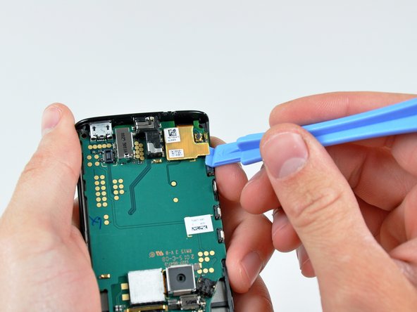
    • Sensors near the top of the board face outward from the front of the phone near the earphone opening.

    • A proximity sensor turns off the touch screen when the phone is against your face.

    • A light sensor automatically adjusts the LCD brightness for optimal viewing in any lighting condition.

  13. Sony Ericsson Xperia X10 Mini E10i Teardown: step 13, image 1 of 2 Sony Ericsson Xperia X10 Mini E10i Teardown: step 13, image 2 of 2
    • Further prying around the perimeter of the front panel assembly allows the LCD assembly to be separated from the front panel.

  14. Sony Ericsson Xperia X10 Mini E10i Teardown: step 14, image 1 of 2 Sony Ericsson Xperia X10 Mini E10i Teardown: step 14, image 2 of 2
    • The digitizer is manufactured by Synaptics, with the main touch screen controller labeled as T1021A 1 0942 AC0P876.

    • Interestingly enough, this is similar to the digitizer found in Microsoft's Kin Two.

    • A Samsung LMS255GF02 takes care of the Mini E10i's display needs.

  15. Sony Ericsson Xperia X10 Mini E10i Teardown: step 15, image 1 of 1
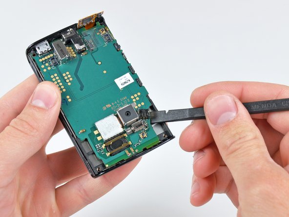
    • And just like that, the dark deed has been done.

    • Thanks, Sony, for keeping it simple.

    • For more information on this little guy, check out EDN's Xperia X10 Mini Preview.

    • Keep an eye on our Teardown page for the arrival of the highly anticipated iPhone 4.

14 Comments

he great take apart, do you need to dissemble the whole phone to replace the power button cap?

Alex - Reply

More or less. It's been a while since I took this apart, but I think you'll have to take the logic board out (work up to step 9). Luckily, this phone is really straightforward to disassemble.

Andrew Bookholt -

so you can't use BST-38 Size: (5.5 x 48 x 40 mm) battery instead that one you have on the picture (or BST-41 some sellers on Ebay say it is compatible) ???

Konstantin K - Reply

great guide, helped me replace a squashed LCD screen by working through and then going in reverse, thanks!

sgtbrom - Reply

Hi There

This is a fantastic guide, and has enabled me to get the battery out, does anyone know where on earth I can buy one of these, I have searched all the usual channels, google ebay etc, but can only find batteries for other models that look nothing like this.

Any help would be much appreciated

All the best - Trev

Trevor Woodgate - Reply

Add Comment

View Statistics:

Past 24 Hours: 0

Past 7 Days: 7

Past 30 Days: 58

All Time: 473,869