Introduction
A multimedia LCD projector from Sony, the VPL-ES1.
This Teardown may help you fix/ replace many items that could possibly go wrong with this unit - Replacing the lamp, to changing the Automatic Lens Door and so on.
It's amazing just ho much they fit into these things- reminds me of what i like to call Chinese Tetris. Although Sony is a very Japanese Co.
-On to the fun-
What you need
-
-
The Front view, Side view w/ Power input, Audio in, Coax in, VGA in and VGA out. Along with Zoom and Focus Dials
-
-
-
The Bottom View
-
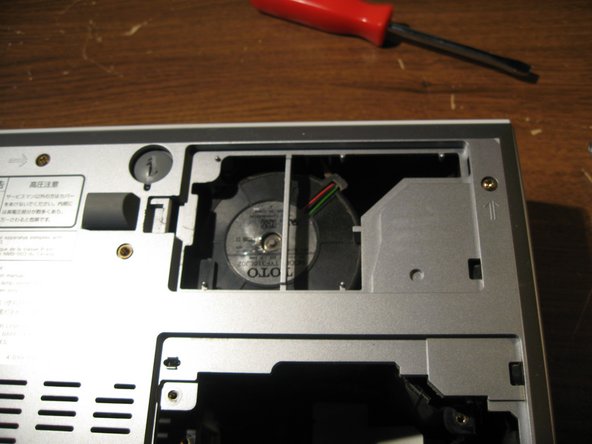
First we are going to remove the Lamp by removing the screw in the first image, and opening and removing the door to the lamp
-
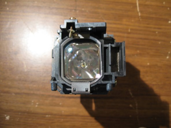
Then we unscrew the two screws on the lamp. they do not completely disconnect from the lamp. So they will remain attached after unscrewing them.
-
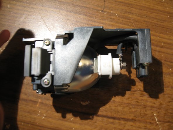
Then lift up on Lamp Handle to remove Lamp from projector assmebly
-
-
-
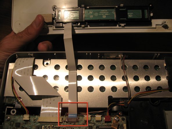
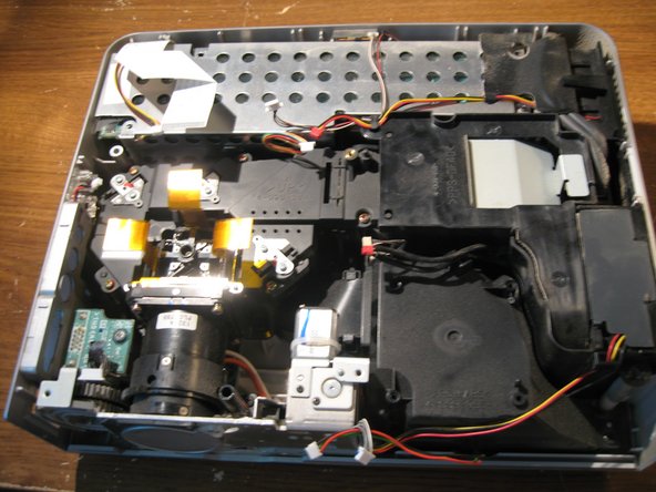
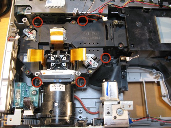
Now you will remove all other connectors from the outer parts of the mainboard. as marked in the Red Rectangles. Gently, pull them out of their connection place.
-
There is one connector from the mainboard to the little blue board in the bottom righthand corner that is connected on the underside of the mainboard. Just disconnect this one from at the blue board.
-
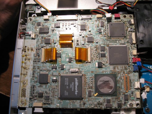
You will find that the two connectors labeled in a yellow rectangle are not connected to anything leading me to believe that this mainboard may be used with other model projectors as well.
-
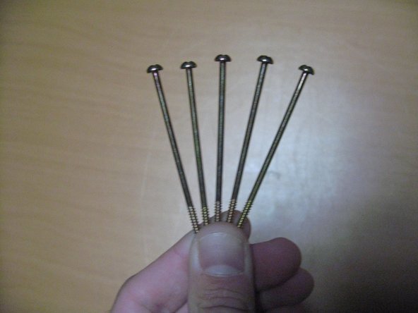
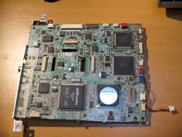
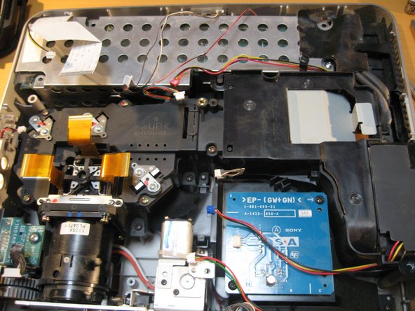
Remove the five screws marked in the red Circles from the mainboard.
-
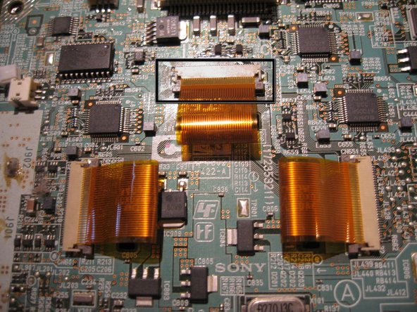
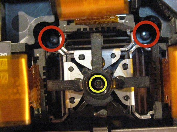
In the Third image you will find the LCD Ribbon Cable on the Center of the Board. You will remove the three of the cables by gently pulling up on either side of the tiny brown connectors attching them to the board
-
-
-
-
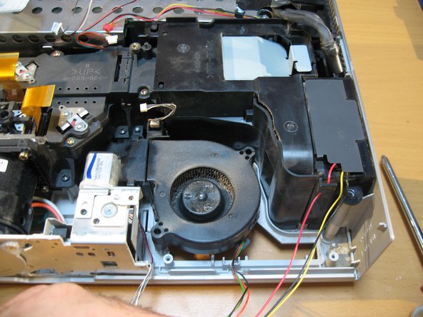
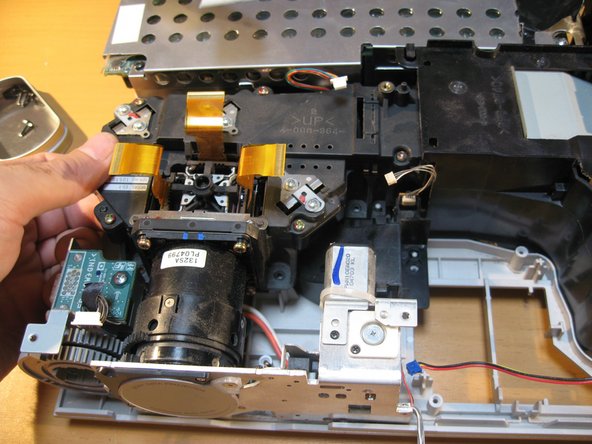
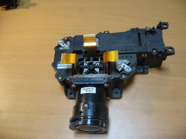
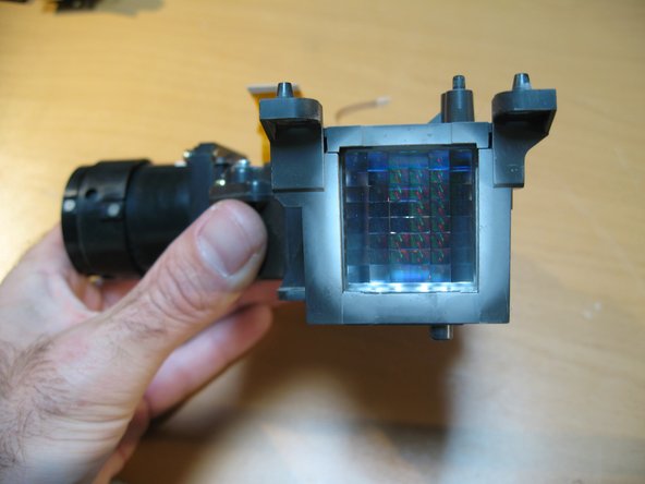
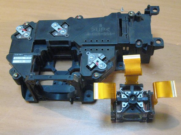
have a look at some of our main components. The LCD and Prism connected to the Lens as well as some of the cooling Channels.
-
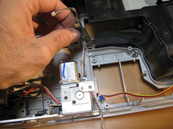
You can opt to remove this little board from a fan shroud but i chose to leave it attached
-
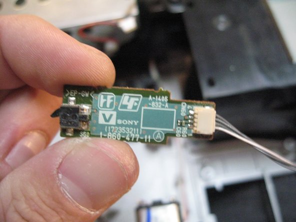
I removed it to show you what it looks like anyway.
-
I removed it to show you what it looks like anyway.
-
-
-
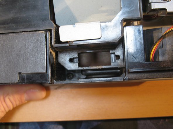
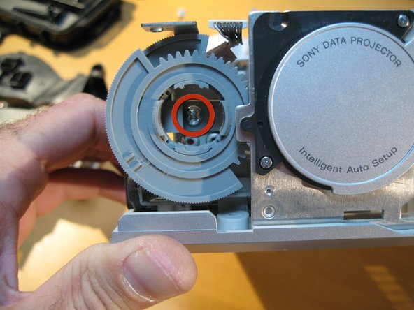
Now we are going to look at removing the Automatic Lens door/Cap and Zoom/Focus Dials
-
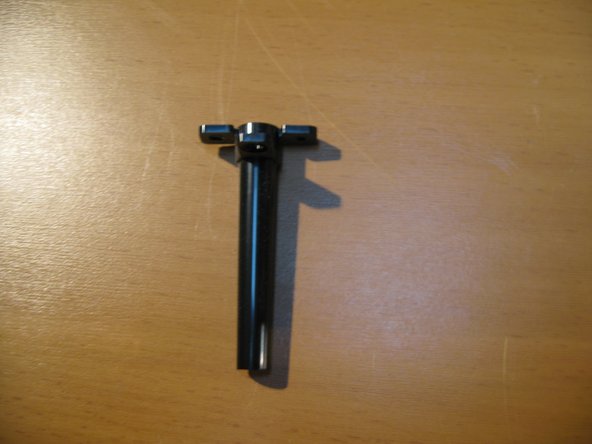
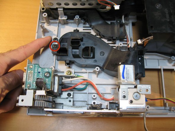
We must remove the Zoom/Focus Dials first in order to proceed. Remove the one screw as labeled in the red circle. and gently remove the two dials out together
-
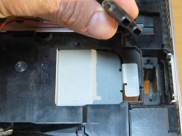
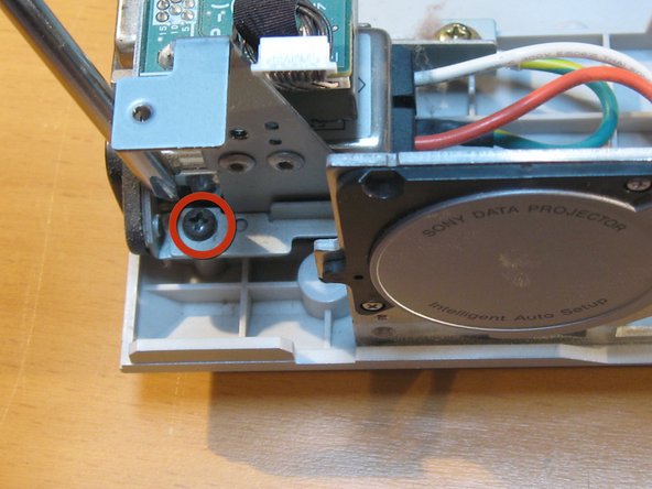
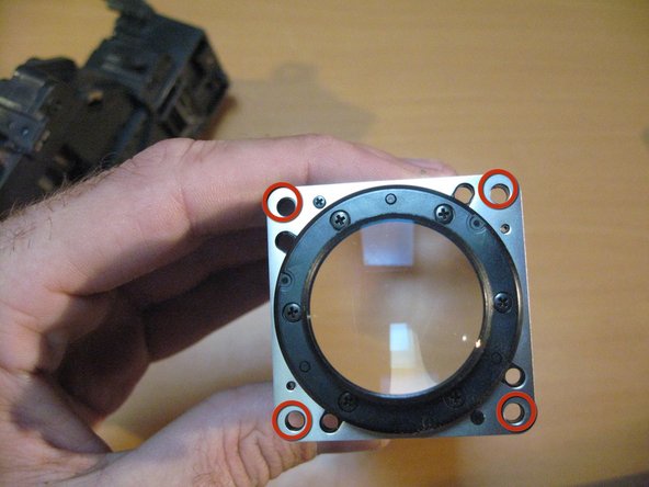
Next to remove the screw holding the Autolens Cap to the rest of the unit.
-
-
-
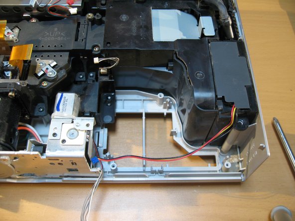
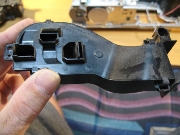
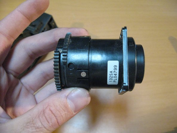
Now you can remove the Autolens cap with motor attached( on the right)
-
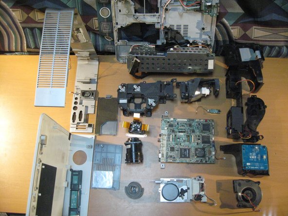
The second image is just a view of what is left on the Unit from the left hand side.
-
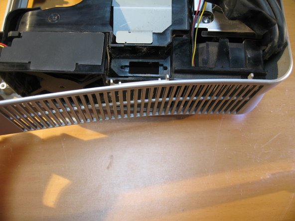
This 3rd pic has another interesting Fan channel from the left underside of the Power supply to the Lamp assembly in two different chutes.
-


4 Comments
Hi, Thanks for such a detailed teardown. Appreciated!
I have a Sony VPL-DW120 projector. Last time, when I just pressed the remote power on button, the projector made a pop or cracking sound. Afterwards no indicator light on the panel is seen and it's not powering on at all; changed power cables and input socket but in vain. Is there any fuse which needs to be replaced or my motherboard gone? Please advise.
Regards,
hey can i ask a quick question? i’ve got a broken microswitch to replace, the one that’s used when opening the shutter. it’s an AV4 4b but i can’t find these anywhere. do you know where i can get one or a good alternative??
dear sir i have an important question can you send a message on instagram to me my name viuna.company thanks